ST.US.E10141.4 USER GUIDE TT1280 and TT1282 HD Professional Receiver/Decoder Software Version 2.0.0 (and later) ENGLISH (UK) www.tandbergtv.
TT128x High Definition Professional Receiver/Decoder Trademarks Dolby® / Dolby® Digital / AC-3® are registered trademarks of Dolby Laboratories Licensing Corporation. Customer Services Europe, Middle East and Africa: Tel: +44 (0) 23 8048 4455 Fax: +44 (0) 23 8048 4467 support@tandbergtv.com Americas: Tel: +1 (321) 308 0470 fieldservice-americas@tandbergtv.com China: Tel: +86 10 6856 0260 (Beijing) Tel: +852 2530 3215 (Hong Kong) fieldservice-asia@tandbergtv.
TT128x High Definition Professional Receiver/Decoder Contents 1 1.1 1.2 Who Should Use This User Guide? ................................................. 5 What Equipment is Covered by This User Guide? .................................. 5 Hardware and Software Options ......................................................... 6 2 2.1 2.2 2.3 2.4 2.5 Installing the Equipment............................................................... 7 Introduction ......................................................
TT128x High Definition Professional Receiver/Decoder List of Tables Table 1.1: Equipment Model Descriptions.................................................... 5 Table 1.2: Hardware Options .................................................................... 6 Table 1.3: Software Options ..................................................................... 6 Table 2.1: Types of Connector................................................................... 8 Table 2.2: Fuse Type and Rating ...................
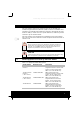
TT128x High Definition Professional Receiver/Decoder 1 Who Should Use This User Guide? This User Guide is written for operators/users of the TT1280 and TT1282 Integrated Receiver/Decoder (IRD) to assist in installation and operation. The TT1280 and TT1282 are referred to throughout this User Guide as ‘IRD(s)’ unless there is a specific difference, where they will be referred to by the model number. This User Guide is not intended to be a detailed source of information.
TT128x High Definition Professional Receiver/Decoder 1.2 Model Number Marketing Code Description TT1282 Common Interface TT1282/CIBAS MPEG-2 HD Decoder with integrated Common Interface CAM reader, AC mains voltage input. MPEG 4:2:0 and 4:2:2 video decode. TT1282 Director (-48 V version) TT1282/DIRBAS/48V MPEG-2 HD Decoder with integrated Director Smartcard Reader, -48 Vdc voltage input. MPEG 4:2:0 and 4:2:2 video decode.
TT128x High Definition Professional Receiver/Decoder 2 Installing the Equipment 2.1 Introduction For best performance and reliability follow the instructions for site requirements and installation in the Reference Guide and only use installation accessories recommended by the manufacturers. 2.2 Operating Voltage AC Models AC models are fitted with a wide-ranging power supply. It is suitable for supply voltages of 100-120 Vac -10% +6% or 220-240 Vac -10% +6% at 50/60 Hz nominal.
TT128x High Definition Professional Receiver/Decoder WARNINGS 1. The Technical Earth is not a Protective earth for electric shock protection. 2. This unit must be correctly earthed through the moulded plug supplied. If the local mains supply does not have an earth conductor do not connect the unit. Contact Customer Services for advice. 3. Before connecting the unit to the supply, check the supply requirements in Annex B of the Reference Guide. 2.
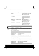
TT128x High Definition Professional Receiver/Decoder Type of Connector Description ASI/HDSDI OUT 1 A 75 W BNC connector provides either an MPEG transport stream output interface or serial digital video output. ASI or HDSDI output format is selectable via the front panel. ASI/HDSDI OUT 2 A 75 W BNC connector provides either an MPEG transport stream output interface or serial digital video output. ASI or HDSDI output format is selectable via the front panel.
TT128x High Definition Professional Receiver/Decoder Connect the Receiver to the power supply as follows: > Power Supply > Receiver > Supply Cord Ensure the power supply is isolated and switched off. Ensure the correct fuse type and rating has been fitted to both the equipment and the power cable. Connect the lead to the Receiver input connector and then to the power supply. Switch on the power supply. Table 2.
TT128x High Definition Professional Receiver/Decoder 3 Operating the Equipment From the Front Panel 3.1 Introduction The front panel display and keypad may be used to configure, control and monitor the Receiver when an external control system is not used. 3.2 Local Control At power-on the Receiver runs through a boot sequence (boot time is approximately 15 seconds). The Service menu is displayed (Menu 3). 3.
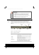
TT128x High Definition Professional Receiver/Decoder 3.4 Navigating the Menus Operating the IRD from the Front Panel is via two operating modes: Navigate Mode and Edit Mode. 3.4.1 Navigate Mode Navigate mode allows the user to move between menus and pages within menus (editing the left display area). Table 3.1: Navigate Mode Action Result Up Pushbutton Pressed Go to page given by uplink of current page, obtain and display current data.
TT128x High Definition Professional Receiver/Decoder Table 3.2: Edit Mode Action Result Up Pushbutton Pressed Increases value of current edit parameter by one unit. Down Pushbutton Pressed Decreases value of current edit parameter by one unit. Left Pushbutton Pressed Moves cursor one edit parameter/parameter digit left (making that the current edit parameter). Right Pushbutton Pressed Moves cursor one edit parameter/parameter digit right (making that the current edit parameter).
TT128x High Definition Professional Receiver/Decoder Table 3.3: Selecting a Menu Option 3.5.2 Step Action Result 1 Select the menu and display the required selection. Normally there is only one selectable item. If there is more than one, use the Right and Left pushbuttons as described in Table 3.4. 2 Press Edit on the front panel. The Save button comes on to show that the new option can be stored. 3 Use the arrow pushbuttons to step through the options.
TT128x High Definition Professional Receiver/Decoder 4 Menu Structure SWITCH ON 1. Presets Menu Boot Screen 1 Presets Select 1.1 Presets Save TT1280 Initialising 2. Input Menu 1 Preset Menu 2 Input Menu 3 Service Menu 4 Conditional Access Menu 5 TS Output Menu 6 Alarms Menu 7 Systems Menu (QPSK, G.703 or IP or HOM) Section C.9 7 Date/Time 7.1 Setup Operating Mode 7.1.1 LCD Contrast 7.1.2 Serial Remote Protocol 7.1.3 IP Address 7.1.3.1 Subnet Mask 7.1.3.2 Gateway Address 7.1.
TT128x High Definition Professional Receiver/Decoder 5 Operating the Equipment Remotely 5.1 Introduction When an external control system is used the Receiver may be configured, controlled and monitored remotely. 5.2 Remote Ethernet (SNMP) Operation If the Receiver is to be controlled via its Ethernet interface the unit's IP address and associated parameters must be set in the relevant menus. Firstly, the unit’s IP address should be set (Menu 7.1.3). Then the unit subnet mask should be set (Menu 7.1.3.
TT128x High Definition Professional Receiver/Decoder HOM/QPSK Input > > > > > > > > Select the RF Input connector (Menu 2.3) Set the LNB frequency (Menu 2.3.2) Satellite frequency (Menu 2.3.2.1) Symbol rate (Menu 2.3.2.2) Modulation FEC (Menu 2.3.2.3) LNB power (Menu 2.3.2.4) LNB 22 kHz (Menu 2.3.2.5) Frequency search range (Menu 2.3.2.6) IP Input > > > > > 6.2 Receive UDP port number (Menu 2.3.2) Input IP address (Menu 2.3.2.1) Input subnet mask (Menu 2.3.2.2) Input gateway address (Menu 2.3.2.
TT128x High Definition Professional Receiver/Decoder 6.5 Select a Service Navigate to the Service Selection menu (Menu 3). For single service transport streams the service should be selected and displayed along with the service ID. For fully compliant DVB or ATSC transport streams the service name should also be displayed. For multiple service transport streams press Edit and, using the Up and Down pushbuttons, scroll through the service name list. Then press Save to select the required service.