
TV Receiver User Manual

TT128x High Definition Professional Receiver/Decoder
9
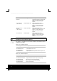
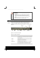
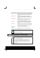
Type of Connector Description
ASI/HDSDI OUT 1
A 75 W BNC connector provides either an MPEG
transport stream output interface or serial digital video
output. ASI or HDSDI output format is selectable via the
front panel.
ASI/HDSDI OUT 2
A 75 W BNC connector provides either an MPEG
transport stream output interface or serial digital video
output. ASI or HDSDI output format is selectable via the
front panel.
ASI/SMPTE 310 IN
A 75 W BNC connector provides an MPEG transport
stream input interface. ASI or SSI (SMPTE 310) input
format is selectable via the front panel.
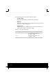
10/100BaseT
An 8-way RJ-45 connector provides a 10/100BaseT
Ethernet interface for external control and monitoring.
Also optionally provides a High Speed Ethernet data
output
Alarm Relay
If required, connect an external status monitoring device
to the Alarm connector. A 9-way, D-type male connector
provides an alarm relay interface which can be used to
send a signal to remote equipment.
RS-232/RS-422
Data Out
RS-232 data is available on the Base Board.
Technical Earth Connect the Receiver's Technical earth to a suitable
point.
2.5 Connecting the Receiver to the Power Supply
NOTE
Refer to the Reference Guide for all power supply, fuse, safety, EMC
information and operating conditions.
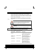
WARNINGS
1. Do not overload wall outlets and extension cords as this can result
in a risk of fire or electric shock.
2. As no mains switch is fitted to this unit, ensure the local power
supply is switched OFF before connecting the supply cord.
3. The Receiver is not fitted with an on/off switch. Ensure that the
socket-outlet is installed near the equipment so that it is easily
accessible. Failure to isolate the equipment properly may cause a
safety hazard.