User Manual Software version F3 D13721.
D1372102_T550_MXP_User_Manual Trademarks and Copyright All rights reserved. This document contains information that is proprietary to TANDBERG. No part of this publication may be reproduced, stored in a retrieval system, or transmitted, in any form, or by any means, electronically, mechanically, by photocopying, or otherwise, without the prior written permission of TANDBERG.
User Manual Environmental Issues Thank you for buying a product, which contributes to a reduction in pollution, and thereby helps save the environment. Our products reduce the need for travel and transport and thereby reduce pollution. Our products have either none or few consumable parts (chemicals, toner, gas, paper) and low energy consuming products.
D1372102_T550_MXP_User_Manual Operator Safety Summary For your protection, please read these safety instructions completely before operating the equipment and keep this manual for future reference. The information in this summary is intended for operators. Carefully observe all warnings, precautions and instructions both on the apparatus and in the operating instructions.
User Manual ISDN cables - CAUTION - To reduce the risk of fire, use only No. 26 AWG or larger telecommunication line cord. Servicing - Do not attempt to service the apparatus yourself as opening or removing covers may expose you to dangerous voltages or other hazards, and will void the warranty. Refer all servicing to qualified service personnel.
D1372102_T550_MXP_User_Manual Contact us If you have any questions, comments or suggestions, please see the Online Support service at www.tandberg.net It is also possible to send a fax or mail to the attention of: Product and Sales Support TANDBERG P.O.
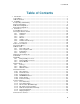
User Manual Table of Contents 1 Introduction............................................................................................................................... 1 1.1 At a Glance ............................................................................................................................ 3 1.2 Menu Structure ...................................................................................................................... 5 2 Installation ......................................
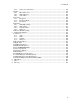
D1372102_T550_MXP_User_Manual 3.12.1 Request Floor and Release Floor............................................................................ 74 3.12.2 Conference Layout................................................................................................... 75 3.12.3 Terminal Names....................................................................................................... 76 3.12.4 Chair Control........................................................................................
User Manual 5 6 7 8 4.5.3 Alert Tones and Volume ........................................................................................ 149 4.6 Video .................................................................................................................................. 150 4.6.1 MCU Status Line.................................................................................................... 151 4.6.2 Web Snapshots.............................................................................
1 Introduction The TANDBERG 550 MXP provides essential video features for face to face meetings for small groups and offices with the quality and reliability found in all TANDBERG equipment. Audio Quality High-performance audio provides a richer, more complete visual communication experience. The MPEG4 AAC-LD standard is used to provide true standards-based CD-quality audio.
D1372102_T550_MXP_User_Manual The TANDBERG videoconferencing system can also be used purely as an audio-bridge (with an ISDN connection). Presentations The Natural Presenter Package* (NPP) makes it possible to run presentations and comprises: Digital Clarity which provides presentations of exceptionally high quality resolution video. PC SoftPresenter which shows PC images via the LAN connection supporting XGA resolution.
Introduction 1.1 At a Glance Camera The built-in camera includes a high quality color camera with a fast pan/tilt/zoom action. The camera is controlled by the system's infrared remote control and operates pan/tilt and zoom. Codec The codec is the heart of the system.
D1372102_T550_MXP_User_Manual Microphone The high quality table microphone is designed to be placed on a table during a videoconference. The ideal location for the microphone is on a flat surface at least 2m (6.5 ft) from the front of the system. The microphone cable should always point towards the system. The system will automatically equalize sound levels. Loud and soft voices are picked up and transmitted to the far end at approximately the same level.
Introduction 1.2 Menu Structure The menu structure is divided in two. The Main Menu is available for all users and contains all functionality of the system. The Administrator Menu contains all the settings of the system. The Administrator Settings are accessible from the Main Menu by selecting Control Panel and Administrator Settings. Making changes to the Administrator Settings will change the behavior of the system. The menu structure for Main Menu and Administrator Settings is shown below.
D1372102_T550_MXP_User_Manual 6
2 Installation Precautions: Never install communication wiring during a lightning storm. Never install jacks for communication cables in wet locations unless the jack is specifically designed for wet locations. Never touch uninstalled communication wires or terminals unless the telephone line has been disconnected at the network interface. Use caution when installing or modifying communication lines.
D1372102_T550_MXP_User_Manual 2.1 Unpacking and Mounting The TANDBERG 550 MXP consists of the following items: Videoconferencing system with built-in camera Table Microphone Remote Control Batteries User Manual on CD Cables Place the system centrally, on top of the monitor, close to the front and ensure it is stable.
Installation 2.2 Connecting Cables 1. Microphone cable Connect the microphone to the microphone cable. Connect the microphone cable to microphone input 1 on the system. 2. Monitor cable(s) Scart (Europe): Connect the Scart adapter to one of the Scart connectors on your monitor.
D1372102_T550_MXP_User_Manual 3. ISDN cables Connect the ISDN cables to the ISDN sockets (S/T-interface) provided by the service provider. The main number will be the number associated with the socket to which ISDN cable number 1 is connected. Note! Some systems and software versions do not support four ISDN lines. North America: The system does not have a built-in network terminator.
Installation Note! Make sure the card is inserted in the right direction (with the product logo pointing upwards). Push the card into the slot until the 'Eject' button pops up. Please see Wireless LAN Settings for configuration.
D1372102_T550_MXP_User_Manual 2.3 Monitor Configuration Power on Power on the monitor and use the monitor remote control to select the Audio/Video input used (refer to the monitor manual). If using S-video from the system, remember to select S-Video input to avoid a black and white picture. Select Audio/Video input on monitor Selection of Audio/Video input used is generally performed by pressing the 0/AV button on the TV remote control several times.
Installation 2.4 System Configuration The system must be configured for each installation unless TANDBERG Management Suite (TMS) is used to configure the system. Configuration settings can be made via the system menu. Navigate through the menu system using the arrow keys and OK. Remember to press the Save button on the bottom of each menu to save the changes. Press Cancel (x) to return to the previous Menu. See General Use for more information about how to use the menus and the remote control.
D1372102_T550_MXP_User_Manual using 16:9 monitors. Picture outside Picture provides a display layout optimized for wide screen monitors. The display layout may be changed at any time using the Layout button on the remote control. 6. Software Options To activate all options for the system, a new option key must be entered in the Software Options menu (see paperwork accompanying the system). The Presenter option key should be entered under “New Option Key”.
Installation Remember to save any changes made in the menu by selecting the Save button on the Menu line and pressing OK.
3 General Use Wake up the system When the system is not in use, it is in standby mode and the screen(s) are black. Wake up the system by picking up the remote control. An incoming call or pressing any key on the remote control will also wake up the system. If the system does not respond: Make sure that the system is switched on by using the On/Off switch located at the rear of the Codec. Verify that your monitor is switched on.
General Use 3.1 The Welcome Screen When the system is switched on, the welcome screen will be displayed. The welcome screen presents the menu and displays your main camera image in the background (main camera is system default). The ISDN/IP numbers and the system name are displayed in the upper right corner. The ISDN Number and IP Number are the dial-in numbers of the system.
D1372102_T550_MXP_User_Manual 3.2 Using the Remote Control The system is controlled with a remote control. Think of the remote control as a mobile phone with number keys and call keys. Use the arrow keys and OK to navigate the menu. The system’s most commonly used functions are also accessible directly from the remote control. The Infra Red (IR) sensor for the remote control is located in front of the WAVE II Camera. 1. Mic Off turns your microphone on and off, see Mic off. 2.
General Use see Selfview. 13. Use the Phone Book to store and recall video contacts for easy placement of calls, see Phone Book. 14. Use the red End Call key to end the current call. Pressing this key when not in a call will place the system in Standby mode, see End Call and Standby. 15. Number/Letter keys function in the same manner as with a mobile or cellular phone, see Number and Letter keys. 16. Press Touch tones when you are in a call and need to dial extension numbers etc. (instead of presets).
D1372102_T550_MXP_User_Manual 3.2.1 Navigation Arrow keys and OK Navigate in the menu with the arrow keys on the remote control. The orange selector on screen shows the selected item. Press OK to select. Cancel key In the main menu, pressing Cancel (X) will hide the menu. If the menu is hidden, bring it back with OK. In other menus, pressing Cancel (X) takes you one step back. In an input field, pressing Cancel (X) will delete characters/numbers to the left.
General Use 3.2.2 Selfview The term “Selfview” means the outgoing image. In a normal call, using main camera, this is the image of your self. The Selfview button toggles the images between Far End, Selfview and Dual Video (if any). How to use Selfview: 1. Outside a call, pressing the Selfview button will switch between the near end video and a black screen on the main monitor. 2.
D1372102_T550_MXP_User_Manual 3.2.3 Layout The layout of the screen can either be shown as Picture in Picture (PIP) or Picture outside Picture (POP) when displaying more than one video image. The behaviour of the Layout button is dependent on the Picture Layout setting in Screen Settings. 3.2.3.1 Picture in Picture When Picture Layout is set to PIP, the Layout button makes it possible to see a second image in a smaller view in one of the corners of the screen.
General Use 3.2.4 Mic Off To mute the microphone during a call, press the Mic off button. An on-screen indicator appears in the upper right corner when the microphone is off. In a call, if audio is detected, the on-screen symbol will start to flash. Pressing the Mic off button one more time will activate the microphone again. Note that Mic off will mute all microphone inputs.
D1372102_T550_MXP_User_Manual 3.2.5 Volume + and - Press the Volume key to adjust the volume level of the codec only and not the monitor. An onscreen indicator will show the current level.
General Use 3.2.6 Number and Letter keys Pressing a number key when outside a call will bring up the call menu. When in a call, the number keys are used for Camera Presets. Press a number and go to the corresponding Camera Preset (see Camera Presets). However, when having an input field where numbers are required, the system automatically goes to number mode and numbers can be dialed with the number keys as usual.
D1372102_T550_MXP_User_Manual 3.2.7 Touch Tones If wanting to dial extension numbers during a call, press the Touch tones button to activate the number keys, otherwise the number keys will activate the corresponding camera presets. An indicator will tell that Touch tones are enabled. Finish with OK to exit Touch tone mode.
General Use 3.3 On-screen Indicators The system has a number of icons signaling different settings: Microphone Off This indicator is shown when the microphone is turned off. Press the Mic off button again to turn the microphone back on, see Mic Off for details. Volume Off This indicator is shown when the volume is turned off. Press Volume + to turn the volume back on, see Volume + and - for details.
D1372102_T550_MXP_User_Manual Telephone This indicates that there is a telephone participant in the conference. The displayed number indicates how many telephone participants there are in the conference.
General Use 3.4 Using the Menu Press the Menu button on the remote control to display the menu. The menu contains all functions needed in order to control the system. The menu contains the following items: Make a Call Standby/End Call Camera Control Presentation MultiSite Services Control Panel Close See Menu Structure for a full overview of the menu. The functions of the menu are displayed as icons.
D1372102_T550_MXP_User_Manual 3.5 Make a Call Display the call menu by either: 1. Select Make a Call from the menu, or 2. Press the green Call button on the remote control The TANDBERG system can make both video calls and telephone calls. Call Settings specifies the quality of the call. It is possible to alter the default call settings for the current call if required. The Default Call Settings are defined in Control Panel - Administrator Settings - Call Quality - Default Call Settings.
General Use 3.5.1 Place Video Call In the Make a Call menu enter the Dial Number either: 1. Manually, or 2. Select the book symbol in order to display the Phone Book and select a conference participant. When dialing manually, toggle between ABC/abc by pressing the # button on the remote control and between abc/123 by holding the # button for one second. Use a star as separator in IP addresses.
D1372102_T550_MXP_User_Manual 3.5.2 Place Telephone Call In the Make a Call menu enter the Dial Number either: 1. Manually, or 2. Select the book symbol in order to display the Phone Book and select a conference participant, see Phone Book for details. When entering a Dial Number manually, toggle between abc/123 by pressing the # button on the remote control for one second. Use a star as separator in IP addresses. Place the call by either: 1.
General Use 3.5.3 Call Settings The Call Settings specifies the quality of the call. Each call will be set up with the Default Call Settings if the settings are not altered. In this case the field is named Default Call Settings. If the settings for some reason are altered for the current participant in the current call, the name of the field will be changed to reflect this. Usually it is not necessary for the user to alter the settings.
D1372102_T550_MXP_User_Manual 3.5.4 Streaming Streaming lets you broadcast your meeting to participants on web. The web participants can listen to the meeting, see snapshots, but not participate themselves. Snapshots of current stream (if MultiSite), selfview, far end and DuoVideo streams are accessible via http. See Appendix 6 for descriptions of the possible snapshot files. Note that on the TANDBERG 550 MXP Streaming is only supported outside a call. How to use Streaming: 1.
General Use TTL/Router Hops Streaming Source* This is used for streaming data to limit how many routers the data should pass before it is rejected. If TTL is set to 2, data will not traverse more than 2 router hops. Auto: Enables streaming of both local and far end video. Selection of which site to be streamed is done using voice switching (the site that speaks is streamed). Local: Only the local video will be streamed. Remote: Only the far end video will be streamed.
D1372102_T550_MXP_User_Manual 3.6 Answer an incoming call How to answer an incoming call: To accept an incoming call, press the OK button or the green Call button on the remote control. How to reject an incoming call: To reject an incoming call, select the Reject icon and press the OK button, or press the End Call button on the remote control. Incoming calls will connect automatically if Auto Answer is set to On, see Auto Answer for details.
General Use 3.7 End Call How to end a call: Press the red End Call button on the remote control, or Press the Menu button on the remote control to display the menu and select End Call. When the End Call dialog box is displayed either: Press the red End Call button on the remote control again, or Press the OK button to confirm that the call is to be ended. Note that switching off the monitor(s), if they may be switched off individually, will not end a call.
D1372102_T550_MXP_User_Manual 3.8 Standby The system will automatically go to Standby mode when it is not in use. In standby mode, the screen(s) are black. It is however still possible to receive incoming calls. How to turn on the standby mode manually: Select Standby from the menu and select Standby Now, or Press the End Call button on the remote control twice.
General Use 3.8.1 Delay Standby for 1 hour Delay Standby for 1 hour postpones the system from entering standby mode for 1 hour. This function is useful when using the monitors for a local presentation to prevent the system from automatically blanking the monitors. It is also possible to postpone the system from entering standby mode for 3 hours, see Delay Standby for 3 hours.
D1372102_T550_MXP_User_Manual 3.8.2 Delay Standby for 3 hours Delay Standby for 3 hours postpones the automatic standby mode for 3 hours. This function is useful when using the monitors for a local presentation to prevent the system from automatically blanking the monitors. It is also possible to postpone the system from entering standby mode for 1 hour, see Delay Standby for 1 hour.
General Use 3.8.3 Do Not Disturb To prevent the system from accepting any incoming calls, the function Do Not Disturb has to be activated. The caller will hear a busy tone when calling the system. The monitor will be black when Do Not Disturb is active, see figure below. End Do Not Disturb by pressing any key on the remote control.
D1372102_T550_MXP_User_Manual 3.9 Phone Book The Phone Book is available via the Phone Book button on the remote control or from the Make a Call menu. Using the Phone Book is time saving and prevents the user from inadvertently calling the wrong number. The contacts are sorted alphabetically. The contact names are displayed in the list and the telephone or video numbers, bandwidth and net profiles of the selected contact is displayed at the bottom line.
General Use Call History My Contacts Global Contacts 43
D1372102_T550_MXP_User_Manual 3.9.1 Call Log The Call Log lists Last Number Dialed, Missed Calls and Call History allows the user to see which calls that are made in the past. The lists contain a maximum of 30 numbers and the numbers are stored in these lists until the system is restarted. If the contacts listed are available in the phone book, the names will be displayed instead of the numbers. Last Number Dialed lists all outgoing calls. Missed Calls lists the calls that are not accepted.
General Use 3.9.2 My Contacts My Contacts are the locally stored contacts on the system. This means that it is possible to add new contacts and edit or delete existing contacts. My Contacts can store up to 200 contacts. How to make a call using My Contacts: 1. Find the desired contact using the arrow keys or searching on the first letter with the letter keys. 2. Press the green Call button on the remote control, or press the left arrow key to select the Call Now icon, followed by OK.
D1372102_T550_MXP_User_Manual The following functions are available from My Contacts: 46 Call Now New Contact Edit Contact Delete Contact Close
General Use 3.9.2.1 Add New Contact The New Contact function is available from My Contacts. Add a new contact to My Contacts by: 1. Select the New Contacts button to open the New Contacts dialog box. 2. Enter Name by using the letter keys on the remote control. Input will automatically be interpreted as letters. Toggle between capital letters and small letters by pressing the # button on the remote control. The maximum name length is 30 characters. For numbers, press the # button for one second. 3.
D1372102_T550_MXP_User_Manual 3.9.2.2 New MultiSite Contact (Optional feature*) The New MultiSite Contact function is available from My Contacts. It is possible to pre-define the participants of a conference meeting as a MultiSite Contact. All participants in the MultiSite Contact will then be connected automatically instead of having to call the participants one by one. My Contacts can hold up to 50 MultiSites Contacts.
General Use Bandwidth for a MultiSite Contact call When calling a MultiSite Contact, the system will try to call the participants with their specified bandwidths. If the total bandwidth exceeds the systems maximum bandwidth, the system will downspeed and distribute the available bandwidth equally for all the participants. Example: In a MultiSite Contact there is one participant with bandwidth 256kbps and one participant with bandwidth 384kbps. 512kbps is the maximum bandwidth of the system.
D1372102_T550_MXP_User_Manual 3.9.2.3 Edit Contact The Edit Contact function is available from My Contacts. How to edit a contact in the Local Phone Book: 1. Select the contact that is to be edited. 2. Press the left arrow on the remote control, followed by the down arrow until the Edit Contact icon is selected. 3. The current settings for this contact is displayed in a dialogue box. Alter the wanted settings. 4. Press OK to save.
General Use 3.9.2.4 Delete Contact The Delete Contact function is available from My Contacts. How to delete a contact: 1. Select the contact that is to be deleted. 2. Press the left arrow on the remote control, followed by the down arrow until the Delete Contact icon is selected. The Delete Contact dialogue box is displayed. 3. Confirm by pressing the OK button again.
D1372102_T550_MXP_User_Manual 3.9.3 Global Contacts When selecting Phone Book the phone book opens showing the Global Contacts below the folders Last Number Dialled, Missed Calls, Call History and My Contacts. Global Contacts are available if the system is connected to an external management system like the TANDBERG Management Suite (TMS). These contacts cannot be changed locally by the system, only from the management system.
General Use 3.9.3.1 Up one Level Global Contacts can be arranged in a tree structure with several sub folders. Use the Up one Level button to navigate up in the tree structure. When a search in the Global Phone Book is made, by using the Search function, only contacts matching the search text are displayed. Select the Up one Level button to return back to the alphabetical list.
D1372102_T550_MXP_User_Manual 3.9.3.2 Search The phone book can contain an unlimited amount of global contacts. Using search makes it easier to find the wanted contact. How to search in the Global Phone Book: 1. Select the Search icon. 2. Enter search text in the dialogue box that appears and press the OK button on the remote control. The system will list all entries that contain the entered letter combination. 3.
General Use 3.9.3.3 Copy Contact to My Contacts The Copy Contact to My Contacts function is available from the Last Number Dialed, Missed Calls, Call History and Global Contacts folders, see Phone Book for details. It may be wise to copy contacts that are often used to My Contacts. Note that the local copy will not be updated if the Global Contacts are updated from the management system. How to copy a contact from the Global Phone Book to the Local Phone Book: 1.
D1372102_T550_MXP_User_Manual 3.10 Camera Control There are several ways to control the camera: 56 Control the camera directly with the arrow keys when the menu is closed or use the Move Camera function in the menu to control both the near end and far end camera, see Move Camera and Far End Control for details. Use the zoom button on the remote control will zoom the picture in (+) and out (-). Use Camera Presets, see Camera Presets for details.
General Use 3.10.1 Move Camera It is possible to move the camera with the remote control or via the menu. Moving the camera directly with the remote control When the menu is hidden, the arrow keys will work on the camera. If the menu is displayed, press the Cancel button on the remote control to hide it. Use the left and right arrow keys to pan the camera, and the up and down arrow keys to tilt the camera. Use zoom + and – to zoom in and out. Moving the Camera via the menu: 1. 2. 3. 4.
D1372102_T550_MXP_User_Manual 3.10.2 Far End Control Far End Control allows you to control your conference partner’s camera. Far End Camera Control is useful if e.g. it is not possible to see what a participant at the far end is writing on their white board. Use Far End Control to move the far end camera and zoom closer on the white board. Use the left and right arrow keys to pan the camera, and the up and down arrow keys to tilt the camera. Use zoom + and – to zoom in and out.
General Use 3.10.3 Camera Presets Use camera presets to easily vary between predefined near end camera angles. This is useful when pictures from many different camera angles have to be sent to the far end. E.g. in a meeting there is a white board, a PC and a small meeting table. Use camera presets to move between these camera angles in order to present the correct information to the participants at the far end without having to move the camera manually every time.
D1372102_T550_MXP_User_Manual 3.10.4 TANDBERG Tracker How to save presets for the TANDBERG Tracker: 1. 2. 3. 4. Select which camera preset to be used on the TANDBERG Tracker. Move the camera to the desired position to store on the tracker. Select Move Camera - Save New Preset in the menu. All camera presets are accessible from the TANDBERG Tracker. For more information, see separate instructions included with the TANDBERG Tracker.
General Use 3.10.5 Picture Control Focus, Brightness and White balance are set for auto focus, auto brightness and auto white balance by default. If you need to set focus, brightness and white balance manually, go to Picture Control in the Camera Control menu. Focus Auto Auto focus continuously updates the focus throughout the call. When moving the camera, the system will use auto focus for 5 seconds to set the right focus of the new camera position.
D1372102_T550_MXP_User_Manual 3.10.6 Camera Tracking Through Camera Tracking and the use of two or three microphones, the camera can automatically position itself on the current speaker. Before using camera tracking, the camera positions used must be stored at Preset 7 (Mic1) and Preset 8 (Mic2). How to use Camera Tracking: 1. Select the Camera Control icon in the main menu. 2. Enable Camera Tracking by choosing Camera Tracking. An indicator will appear on the screen. 3.
General Use 3.11 Presentation The Presentation Functionality in the system enables you to show other available video sources in addition to your Main Camera. This is perfect for meetings where you would like to show a PowerPoint presentation for instance. You can even use arrow keys up and down on the remote control to activate Page Up/Down on the PC (this only applies when using VNC). Use Presentation outside a call to make a local presentation for the people in your own meeting room.
D1372102_T550_MXP_User_Manual 3.11.1 Presentation Key The quickest way to show a presentation is to use the presentation key on the remote control. The presentation key is used to start and stop a presentation. The presentation key will display PC (default*) or the last used presentation source. When holding the presentation key for 1 second, the presentation menu will be displayed. This menu allows you to choose other video sources.
General Use 3.11.2 Presentation Menu The Presentation menu offers you all available video sources; Main Camera, PC, Document Camera, VCR, AUX and VNC. All these sources can be used as Main Video Stream or Dual Video Stream (Duo Video / H.239). Not all systems has all video sources available, see Interfaces for details. Outside a call the presentation menu only contains Main Video Sources. In a call, the headers Dual Video and Snapshot display in addition to Main Video (if the call supports Duo Video /H.
D1372102_T550_MXP_User_Manual 3.11.3 PC Presenter (DVI/XGA Input) (Optional feature - not available on all systems) Users often have their presentations on a laptop that is brought into the meeting room. Remember to connect your PC to the codec before you press the Presentation button. Note that the image will appear smoother on the system if your presentation is already displaying in full screen on your PC prior to connecting your PC to the video system.
General Use 3.11.4 PC Soft Presenter and VNC (Optional feature) PC SoftPresenter is used to display PC images on your system without using a VGA cable (PC Presenter). The system and your PC must be connected to the same LAN. In addition, VNC (Virtual Network Computing) server software must be installed on the PC. Free software can be downloaded from http://www.realvnc.com. Install the software by running the downloaded file. How to configure the VNC Server software: 1.
D1372102_T550_MXP_User_Manual 3.11.5 Dual Stream (DuoVideoTF/H.239) (Optional feature - not available on all systems) With Dual Stream you have the opportunity to show two different live video streams simultaneously, main video and one additional source. This is handy when showing a presentation. You see the live presentation and the live video of the presenter simultaneously. When you start a presentation, Dual Stream starts automatically if both local and remote system supports Dual Stream.
General Use 3.11.6 Take New Snapshot The system can take a snapshot of your live video. Snapshot is handy when you are in a call with a system that does not support Dual Stream. Use Snapshot to show a snapshot of your presentation and continue the meeting with main camera. How to use snapshot: You find Take New Snapshot in the Presentation menu. 1. Select the Snapshot header. 2. Select Take New Snapshot and press OK to take a snapshot. Snapshot is found on the Star key on the remote control. 1.
D1372102_T550_MXP_User_Manual 3.11.7 Display Snapshot The system stores the last sent or received Snapshot. The snapshot is deleted automatically after the call. How to display snapshots: 1. To view a stored snapshot, first choose the Snapshot header. 2. Select Display Snapshot in the Presentation menu. 3. Press the Display Snapshot button again to deselect it. When disconnecting the call, the stored snapshot will be erased. Receiving snapshots: 1.
General Use 3.12 Conference Services A Multipoint Control Unit (MCU) enables several sites to participate in the same conference. During an MCU conference, the status line will provide information about the conference. You can make a multipoint conference in different ways. The Conference Services vary depending on how you make the call, see Add call for details.
D1372102_T550_MXP_User_Manual Example of MultiSite for mid- to low end systems Using the system’s internal MCU, MultiSite TF * Most TANDBERG MXP systems has an optional built-in MCU, which is called MultiSite*. It supports up to 6 video calls and 5 telephone calls including yourself for high-end systems, and 4 video calls and 3 telephone calls including yourself for the mid- and lower end systems. The MultiSite supports both Split Screen and Voice Switched mode.
General Use Using an external MCU with limited Chair Control Support you may have the following services With an external MCU that does not support H.
D1372102_T550_MXP_User_Manual 3.12.1 Request Floor and Release Floor When requesting floor, your video will be broadcasted in full screen to all other participants in the conference. Request Floor is useful when you want to speak or display something in front of all participants. Release Floor when you are done and make the floor available for other participants in the conference. An indicator appears when you have floor and disappears when you release floor, see floor indicator in On-screen Indicators.
General Use 3.12.2 Conference Layout (Only supported by TANDBERG MultiSite*) With a TANDBERG MultiSite you can choose between the layouts: Auto Split, 4 Split, 5+1 Split and Voice Switched view. Auto Split displays all participants on the screen simultaneously. 4 Split displays the 4 last speaking Participants including the MultiSite host. 5+1 Split displays the speaking participant in a big picture and the other participants in small pictures.
D1372102_T550_MXP_User_Manual 3.12.3 Terminal Names Choose Terminal Names to see a list of the participants of the MultiSite conference. Press Cancel to go back.
General Use 3.12.4 Chair Control (Not supported by TANDBERG MCU, TANDBERG MPS or MultiSite) As chairman, you have access to more MultiSite Services. Select Chair Control to assume the role of chairman of the conference. Select Release Chair to end the role as chairman. A Chair indicator appears when you have Chair and disappears when chair is released.
D1372102_T550_MXP_User_Manual 3.12.5 Assign Floor and Release Floor from Participant Assign Floor allows the chairman to select which of the conference participants that is to be broadcasted to all other participants.
General Use 3.12.6 View Site and End View (Not supported by TANDBERG MCU or MultiSite) View Site allows you to view any participant in the conference regardless of whom having floor and chair. Choose End View to go back to normal.
D1372102_T550_MXP_User_Manual 3.12.7 Disconnect Participant Disconnect Participant allows the chairman to disconnect any participant in the conference. In a multipoint call, this is equivalent to disconnecting a participant from the end call menu.
General Use 3.12.8 Terminate Meeting Terminate Meeting allows the chairman to terminate the conference altogether. In a MultiSite call, this is equivalent to pressing End All Calls from the end call menu.
D1372102_T550_MXP_User_Manual 3.12.9 More about MultiSite (embedded MCU) (Optional Feature*) Calling in to a MultiSite Any system can be part of a MultiSite conference by calling in to a MultiSite. The dial-in numbers to the MultiSite depends of the network that is used. To dial in to the MultiSite on IP: Dial the IP Number or the IP Address of the system. All sites can dial the same number. To dial in to the MultiSite on ISDN-PRI: Dial the ISDN number of the system.
General Use 3.
D1372102_T550_MXP_User_Manual 3.13.1 Diagnostics Diagnostics allows testing of individual system components and displays the current system settings.
General Use 3.13.1.1 System Information Select System Information to view system numbers, line status, software version, hardware serial number and other useful information. Press arrow key up and down to scroll in the System Information list.
D1372102_T550_MXP_User_Manual 3.13.1.2 Channel Status Comprehensive information about the call progress is available through the Channel Status window. This window indicates the various stages each B-channel goes through whilst establishing a connection.
General Use 3.13.1.3 Call Status Comprehensive information about the call is available through the Call Status window. The menu has two columns, one for transmitted and one for received audio/video/data information. If Dual Stream or MultiSite is available on your system and in use, pressing the UP/DOWN keys will show one page per connected site. Some of the information fields will vary dependent on if H.320 (ISDN calls) or H.323 (IP calls) are made.
D1372102_T550_MXP_User_Manual 3.13.1.4 System Selftest The system performs a check to determine internal hardware integrity. System Selftest is useful when you want to check if your network connection is active.
General Use 3.13.1.5 View Administrator Settings This window displays all the system settings. Use the arrow key on the remote control to scroll through the list.
D1372102_T550_MXP_User_Manual PC Document Camera VCR AUX VNC Split Screen Default Call Settings Call Type Network Bandwidth Restrict (56k) Auto H320 Bandwidth Auto H323 Bandwidth SIP Audio Settings Inputs Mic1 Mic2 Mic3 Audio4 Audio5 Audio6 Mix Mode VCR Ducking Level Settings Mic1 Mic2 Mic3 Audio4 Audio5 Audio6 Outputs Out1 Out2 (AUX) Out3 (VCR) Out1 Mode Level Settings Out1 Out2 (AUX) Out3 (VCR) Echo Control Mic1 Mic2 Mic3 Audio4 Audio Levelling (AGC) Mics Audio5 (AUX) Audio6 (VCR) Received A
General Use White balance Brightness Video Name Main Cam AUX Doc Cam VCR PC VGA VNC Network Type ISDN-BRI\PRI\Leased E1\T1\Enternal H331 ISDN Switch Type ETSI (Euro ISDN),… Line1 Setup On Number1 Number2 SPID1 SPID2 Line2 Setup On Number1 Number2 SPID1 SPID2 Line3 Setup On Number1 Number2 SPID1 SPID2 Advanced ISDN Settings Subaddress Validate Numbers (MSN) Parallel Dial Send Own Numbers Sending Complete ISDN-PRI Settings Number Range ISDN-PRI Switch Type Channel Hunting Max Channels Low Channel Hi
D1372102_T550_MXP_User_Manual IP address IP subnet mask Gateway Ethernet Speed H.323 Settings E.164 Alias Use Gatekeeper Gatekeeper IP H.323 Prefix Advanced H.
General Use 3.13.1.6 IP Address Conflict Check The system will give a warning if there is an IP conflict. The user may initiate this check by selecting IP Address Conflict Check.
D1372102_T550_MXP_User_Manual 3.13.1.7 Warnings If any warnings registered by the system it will be displayed in the Warnings menu. Open a warning in the list to get more information about the warning. The following warnings are displayed if detected by the system: ISDN BRI warnings ISDN is enabled on BRI line x, but the line is not connected. Please check your network connection or disable the line. (101) There is something wrong with ISDN BRI line x. Please check your network connection.
General Use There is something wrong with the Leased E1/T1 line (Yellow alarm). Please check your network connection. (193) H323 gatekeeper warnings Could not register to the gatekeeper. The gatekeeper rejected to register the system. Another system is already registered with the same alias or H.323 ID. The max capacity on the gatekeeper is reached. Registration failed. Tried to register to the gatekeeper without a valid alias. Registration failed.
D1372102_T550_MXP_User_Manual 3.13.2 Text Chat While in an ISDN or IP call to another system supporting Text Chat (T.140), select Text Chat from the Control Panel. Enter text in the displayed window. How to use Text Chat: 1. Choose Text Chat from the Control Panel to open the Text Chat window. 2. Enter text with the number keys like on a mobile phone. The text is sent to the far end continuously letter by letter. 3. Press OK to end Text Chat and escape from the text chat window.
General Use 3.13.3 Audio Demo Note that the Audio demo will only appear in the User Guide if a Digital Natural Audio Module is connected to the codec.
D1372102_T550_MXP_User_Manual 3.13.4 Administrator Settings Administrator Settings contains the configuration of the whole system. It is recommended to password protect Administrator Settings to prevent occasional users to make changes to the system. See Administrator Settings for further details.
General Use 3.13.5 Restart Restart the system by pressing the Restart button. You are prompted with a dialog box saying: Do you want to restart the system? Press OK to restart, press Cancel (X) to abort.
D1372102_T550_MXP_User_Manual 3.13.6 User Guide The on screen user guide takes you through a quick step-by-step introduction to videoconferencing. It gives the user basic skills in how to use the system.
4 Administrator Settings Administrator Settings contain all the settings of the system. Making changes to Administrator Settings will change the behavior of the system. It is recommended to password protect the access to Administrator Settings to prevent occasional users from making crucial changes to the system, see Administrator Password.
D1372102_T550_MXP_User_Manual 4.1 General Settings When installing the system, go through the General Settings menu to ensure that you have the right settings for your system, see System Configuration.
Administrator Settings 4.1.1 Language The system supports 15 different languages for its on-screen menus; English, German, French, Norwegian, Swedish, Italian, Spanish, Portuguese, Chinese Simplified, Chinese Traditional, Japanese, Russian, Korean, Finnish and Thai. Select the preferred language and press OK to save.
D1372102_T550_MXP_User_Manual 4.1.2 System Name System Name identifies the system: On the welcome page. During an MCU conference call. When using the Web-interface. When the codec is acting as an SNMP Agent. Towards a DHCP server. H323 ID. Other systems can call in using this name instead of IP-number/IP-address. System Name is blank by default. System name can be alphanumeric and up to 50 characters long. Follow the installation procedure to enter a System Name.
Administrator Settings 4.1.3 Auto Answer The auto answer setting decides whether an incoming call is put through automatically or manually. On The system will automatically answer all incoming calls. On+Mic Off The system will automatically answer all incoming calls and switch the microphone off when the call is connected. Press Mic Off to switch the microphone on. Off You must manually answer all incoming calls by pressing OK or the Call key.
D1372102_T550_MXP_User_Manual 4.1.4 Max Call Length This feature will automatically end both incoming and outgoing calls when the call time exceeds the specified Max Call Length. Max Call Length can have the following values: 0-999 (minutes), where 0 means off.
Administrator Settings 4.1.5 Phone Book Settings Phone Book On Phone Book is available in the menu. Off Phone Book is hidden from the menu and is unavailable for users. IP address Enter the IP address of the management system that provides the Phone Book. Path The Path indicates the function of the management system.
D1372102_T550_MXP_User_Manual 4.1.6 Permissions Permissions contains settings for incoming telephone Calls, Far End Control, Remote Software Upgrade and Fallback to Telephony. Access Code An access code will help you control the use of the system. All users must enter a code to identify themselves and the call will be charged on their account. Access Codes are handy for group systems where there are more users or divisions that share the costs of using the system.
Administrator Settings On The system will allow a remote system to upgrade local software. Off The system will not allow a remote system to upgrade local software. Note that the configuration can also be done via the telnet or the serial port. Fallback to Telephony When dialing a number and the system fails to place a video call to the number dialed, the system will attempt to place a telephone call if Fallback to Telephony is enabled. On Enables fallback from video calls to telephone calls.
D1372102_T550_MXP_User_Manual 4.1.7 Screen Settings Auto Layout On If Auto Layout is On the system will change layouts automatically depending on the number of participants in a call and if you have a dual video stream or not. Please refer to Layout for more information. Off If Auto Layout is Off there will be no automatic layout changes during a call. All desired layout changes must be done manually.
Administrator Settings Example of Picture in Picture. Example of 1+1 Side-by-Side view (wide screen). Example of 1+2 Picture outside Picture (wide screen). Example of 1+3 Picture outside Picture (wide screen).
D1372102_T550_MXP_User_Manual Note that if both TV monitor format and VGA format is set to Normal, the system will skip the 1+3 layout, which is not beneficial for 4:3 monitors. Note that the following menu settings do not apply for all TANDBERG MXP systems. Please refer to the actual menu page on your system. TV Monitor Format (wide screen monitors only) To fully leverage your wide screen display, activate the Native 16:9 format by setting the TV Monitor Format to Wide.
Administrator Settings Wide screen VGA or TV monitor In Wide (native) mode. VGA Out Quality* The supported range of VGA formats will be optimized for the VGA display monitor based on the source image. VGA Out Quality enables the user to change the preferred format for the DVI/VGA output. It is recommended to keep this setting in Auto unless your screen doesn’t support some of the XGA or SVGA formats the system is using. Note that the VGA Out port support VESA Power Management.
D1372102_T550_MXP_User_Manual Normal VGA output will have 4:3 aspect ratio on wide screen monitor. Wide VGA output will utilize the wide screen monitor at full. PC presentation shown in Normal (correct ratio) mode. PC Presentation shown in Wide (stretched) mode.
Administrator Settings 4.1.8 Software Options The system requires a valid option key to activate MultiSite and/or Presenter functionality. In order to activate additional bandwidth, you need to enter a bandwidth key. A restart of the system is required after entering a new option and/or bandwidth keys. If the key is invalid, the original key will be used. The following options are available: 1. 2. 3. 4.
D1372102_T550_MXP_User_Manual 4.
Administrator Settings 4.2.1 Menu Timeout In Call Main menu appears on the bottom line of the screen. Set Menu Timeout In Call to On if you want the menu to time out automatically when you are in a call. On The menu will time out automatically after 15 seconds if there is no activity on the remote control. Menu timeout does only apply when you are in a call. Outside a call, the menu will not time out. Off The menu will not time out automatically. Press Cancel (X) to hide the main menu manually.
D1372102_T550_MXP_User_Manual 4.2.2 Welcome Menu The Welcome Menu contains the Main Menu, System Status, your System Name and dial in numbers. On The Welcome Menu is shown when the system wakes up from standby mode. Off The Welcome Menu is not shown when the system wakes up from standby mode. Press the OK button to open the welcome menu.
Administrator Settings 4.2.3 Welcome Picture The Welcome Picture is what you see in the background of the welcome menu. Selfview Selfview is shown in the background of the welcome menu. In most cases this means that main camera is displayed and you can see the video image of yourself. Off No picture is shown in the background of the welcome menu.
D1372102_T550_MXP_User_Manual 4.2.4 Logo It is possible to upload a company logo to the system. For more information about how to upload a Logo, see Appendix 6. Set the Logo settings to On to display the logo. On Choose On if you want the company logo to appear in the background of the welcome menu. Off The logo is not displayed. Note: The TANDBERG Logo will be displayed if no other company logo is load and logo is enabled.
Administrator Settings 4.2.5 Menu on TV The Menu on TV setting decides if the menu shall be displayed on the TV screen or not. For optimal layout of the menu, Menu on TV should be Off if Menu on PC is On and vice versa. On The menu is available on the TV screen. Off The menu is not available on the TV screen.
D1372102_T550_MXP_User_Manual 4.2.6 Menu on PC The Menu on PC setting decides if the menu shall be displayed on the PC (VGA screen) screen or not. For optimal layout of the menu, Menu on TV should be Off if Menu on PC is On and vice versa. On The menu is available on the PC screen. Off The menu is not available on the PC screen.
Administrator Settings 4.2.7 Balloon Help It is possible to enable / disable the balloon help window. On Choose On if you want help text windows to appear. Off There will be no help text window.
D1372102_T550_MXP_User_Manual 4.2.8 Display Welcome Text The welcome text displays your system name and dial in numbers by default. It is possible to hide this information by choosing Display Welcome Text Off. On Welcome text is displayed on the welcome menu. Off Welcome text is not displayed on the welcome menu.
Administrator Settings 4.2.9 Welcome Text You can change the welcome text to any text you like, instead of the default text. Remember that Display Welcome Text must be On to be able to edit the welcome text.
D1372102_T550_MXP_User_Manual 4.2.10 Administrator Password It is recommended to put an Administrator Password on the system. The Administrator Password can be maximum 5 digits long. The Administrator Password dialog box will pop up when you choose Administrator Settings from the Control Panel. This will prevent occasional users from going in to administrator settings.
Administrator Settings 4.3 Presentation Settings Presentation Settings contain: H.
D1372102_T550_MXP_User_Manual 4.3.1 H.239 H.239 supports transmission of two video streams. It combines elements of Duo Video and People+Content. If H.239 is disabled you will still be able to start TANDBERG Dual Video Stream* Enabled Enables H.239 Disabled Disables H.239 * The TANDBERG 550 MXP can only receive Dual Video Stream.
Administrator Settings 4.3.2 Startup Video Source The Startup Video Source is the video source on display when the system wakes up from standby mode. If you use Main Camera as start up source, the system will start with Main Camera every time the system wakes up from standby, regardless of what the previous user was using. You can change Startup Video Source to Main Camera, PC, Document Camera, VCR, AUX, VNC or Current depending on what video sources you have available for your system.
D1372102_T550_MXP_User_Manual 4.3.3 Presentation Source The Presentation Source is connected to the Presentation button on the remote. Pressing the Presentation button will put the Presentation Source on display. Presentation Source is PC by default*. You can change the Presentation Source to any video source and none. Choosing none results in opening the Presentation menu when pressing the Presentation key. * Only for systems with the PC video input available.
Administrator Settings 4.3.4 Snapshot Source When you take a Snapshot, you get a snapshot of the Snapshot Source. Current is the default Snapshot Source. This means that you take a snapshot of the video source that is currently active. You can change the Snapshot Source to any video source. In this way you can program the snapshot key to apply only for PC for instance. Press Snapshot and you will take a PC snapshot regardless of what video source that is currently active.
D1372102_T550_MXP_User_Manual 4.3.5 Auto-Display Snapshot Select Auto to automatically display a received snapshot. Turn Auto-Display Snapshot Manual if you wish not to have them displayed on the screen when they are sent or received. The snapshots will be sent and received, but not displayed. With Auto-Display Snapshot set for Manual, you must enter the Presentation menu to display a snapshot. Auto A sent or received snapshot will automatically be displayed on the screen.
Administrator Settings 4.3.6 PIP Appearance A Picture in Picture (PIP) is a smaller picture placed in one of the corners of the screen. The PIP enables you to see an extra picture in your video conference. Auto PIP Auto means that Picture In Picture will appear automatically when it is suitable. A picture in picture is nice when you use Duo Video and you need an extra window to see all the pictures. You can of course show or hide the PIP with the Layout button on the remote anytime.
D1372102_T550_MXP_User_Manual 4.3.7 PIP Placing PIP Placing lets you decide where the PIP shall appear. You can of course move the PIP with the Layout button on the remote anytime. Top Right PIP is placed in the Top Right corner. Bottom Right PIP is placed in the Bottom Right corner. Bottom Left PIP is placed in the Bottom Left corner. Top Left PIP is placed in the Top Left corner.
Administrator Settings 4.3.8 VNC Settings VNC Settings is necessary when using a VNC presentation. See chapter PC Soft Presenter and VNC for more information on how to use VNC. Address The IP-address of the PC with the VNC software installed. To find the IPaddress of the PC, place the mouse pointer on the VNC program icon in the lower right corner of the Windows taskbar. You can also select Command Prompt from the Startup-menu\Run and type cmd then enter. This will open a command window and from here.
D1372102_T550_MXP_User_Manual 4.
Administrator Settings 4.4.1 Video Algorithm The system will automatically select the best video algorithm based on the video source and the capabilities of the remote system. Use this menu to disable video algorithms in case you have interoperability issues calling other systems. H.264 Bandwidth efficient video compression and decompression. H.263 Normal video compression and decompression. H.261 Legacy video compression and decompression. The system will always have H.261 enabled.
D1372102_T550_MXP_User_Manual 4.4.2 Audio Algorithm The system will automatically select the best audio algorithm based on the call rate and the capabilities of the remote system. Use this menu to disable audio algorithms in case you want to remove “low quality” audio, or if you have interoperability issues calling other systems. G.722 High quality audio (7 kHz at 48kbps, 56kbps or 64kbps) G.728 Compressed normal quality audio (telephone quality, 3.1 kHz at 16kbps) G.
Administrator Settings 4.4.3 Natural Video Choosing Natural Video will enable 60 fields* per second true interlaced picture for high motion video. The use of Natural Video requires the H.263+ and H.263++ video protocols. Natural video will be disabled in H.323 MultiSite calls and in H.320 Continuous Presence MultiSite calls. Auto Natural Video Auto will enable transmission of Natural Video from 768 kbps and above. Reception of Natural Video is in this case always enabled.
D1372102_T550_MXP_User_Manual 4.4.4 Max Upstream Rate (kbps) The Max Upstream Rate (kbps) defines the desired maximum transmitted call rate. This is to be able to limit the outgoing bandwidth whilst keeping the maximum incoming bandwidth, especially useful for home offices with different upstream and downstream rates, typically ADSL.
Administrator Settings 4.4.5 Video Quality The different video sources need different Video Quality Settings. Main Camera, VCR, AUX and Split Screen have Motion as default. PC, Document Camera and VNC have Sharpness as default. Motion Optimized for smooth motion video (CIF/SIF for low bandwidths, iCIF/iSIF for high bandwidths). Sharpness Optimized for sharp video (4CIF/4SIF, SVGA, XGA). Auto The system chooses the best of Motion or Sharpness depending on picture layout and bandwidth. 4.4.5.
D1372102_T550_MXP_User_Manual Basic Video Quality Video Input Transmission mode selection rules MOTION PAL iCIF@50 -> CIF -> QCIF MOTION NTSC iSIF@60 -> iCIF@60 -> SIF@60 -> CIF -> QCIF MOTION VGA CIF -> QCIF MOTION SVGA CIF -> QCIF MOTION XGA CIF -> QCIF SHARPNESS PAL 4xCIF -> VGA -> CIF -> QCIF SHARPNESS NTSC 4xSIF -> 4xCIF -> VGA -> SIF -> CIF -> QCIF SHARPNESS VGA VGA -> 4xCIF -> CIF -> QCIF SHARPNESS SVGA SVGA -> 4xCIF -> VGA -> CIF -> QCIF SHARPNESS XGA XGA -> SVGA ->
Administrator Settings 4.4.6 Default Call Settings Default Call Settings are connected with Call Settings in the call menu. If you leave Call Settings unchanged when making a call, the system will use the Default Call Settings in the call. In addition to the Call Settings Call Type, Net, Bandwidth and Restrict (56k), you also find settings for H.320 Auto bandwidth and H.323 Auto bandwidth in Default Call Settings.
D1372102_T550_MXP_User_Manual Select H.323 to ensure that the call is set up as an H.323 call. Select SIP to ensure that the call is set up as an SIP call. Bandwidth Bandwidth decides the quality of the video picture. When set to Auto the system will establish a connection using a proper bandwidth for the call, typically 384kbps for ISDN calls and 768kbps for IP calls. When set to Max the system will set up the call with maximum bandwidth depending on the selected network.
Administrator Settings Set Network to ISDN Set Bandwidth to 128 kbps A field for the 2nd number pops up in Call Settings. Enter the second number in the Call Settings field. For 128 kbps calls that use bonding, ignore the second number field and just enter one number to be dialed. Using sub-address / extension address / MCU password Sub-address is used to address different systems on the same ISDN line and is primarily used in European Countries.
D1372102_T550_MXP_User_Manual 4.
Administrator Settings 4.5.1 Inputs Mic 1 and Audio input 2 By default, both inputs are enabled. Just plug in an audio source and it is active. Audio inputs that are On will automatically be mixed. Unconnected inputs will automatically be muted. Select Off to prevent audio/noise from connected but unused inputs. The activated audio sources are stored on camera presets. Mic 1 is intended for electret type microphones. The microphone inputs are balanced with 24V phantom power.
D1372102_T550_MXP_User_Manual 4.5.2 Output Level Settings The audio out is intended for connection to televisions or audio amplifiers. Digital mode (SPDIF) is supported when configuring the output to SPDIF mode by the web interface or dataport/XML. Adjust the audio output level to the loudspeakers. The volume keys on the remote control also adjust the level of the audio output. Please see Interfaces for details on the audio connectors.
Administrator Settings 4.5.3 Alert Tones and Volume Video Call Alert Tone and Telephone Alert Tone To help distinguish between incoming video calls and ordinary telephone calls, it is recommended to use different ringing tones for video calls and telephone calls. Alert Volume You may change the volume level for the selected ringing tone. Alert Speaker The system also has an internal, call-alerting speaker.
D1372102_T550_MXP_User_Manual 4.
Administrator Settings 4.6.1 MCU Status Line On The MCU indicator will be displayed and provide information about the conference. Off The MCU indicator will not be displayed. Auto The MCU indicator will be displayed for a few seconds and then timed out. When grabbing the remote control, the indicators will be shown again.
D1372102_T550_MXP_User_Manual 4.6.2 Web Snapshots The system is able to generate JPEG snapshots and provide them to the world outside by request (as ‘http get’ or via ftp). See Appendix 6 for descriptions of the possible snapshot files. On Snapshots generation is enabled. Off Snapshots generation is disabled. Note that web snapshots are not generated if the conference is encrypted.
Administrator Settings 4.6.3 Video Name As a default, the video inputs are given the names Main Cam, PC, Doc Cam, VCR, AUX or VNC, dependent on what video sources are available on your system. The video names cannot exceed eight characters. The names correspond to the video names in the Presentation Menu (Choose Presentation from the main menu and open the Main Video or Presentation Video pop up menu).
D1372102_T550_MXP_User_Manual 4.
Administrator Settings 4.7.1 Encryption (Country specific) Auto The system will try to set up calls using encryption. Point to point calls: If the far end system supports encryption (AES or DES), the call will be encrypted. If not, the call will proceed without encryption. MultiSite calls*: In order to have encrypted MultiSite calls, all sites must support encryption. The padlock symbol will indicate encryption mode (AES or DES).
D1372102_T550_MXP_User_Manual 4.7.2 Encryption Mode Auto The system will try to use the most secure encryption - AES, dependent on the capabilities of the other sites. For sites that do not support AES encryption, DES encryption will be tried. AES The system will try to use AES with 128 bits encryption when setting up calls. If AES is not supported by the other site(s), no other type of encryption will be initiated.
Administrator Settings 4.7.3 Passwords Administrator Password, IP Access Password, Streaming Password, VNC Password, Access Code and Remote Software Upgrade password are duplicated from their respective menus. Using the Security menu gives you a quick way to change all passwords of the system.
D1372102_T550_MXP_User_Manual 4.
Administrator Settings 4.8.1 ISDN-BRI Settings To make sure your system will work properly using ISDN-BRI, make the following settings: 1. Set ISDN switch type 2. Enter ISDN line numbers (+ SPIDs if required) 3. Disable unused lines Some software versions do not support 6 ISDN lines, therefore some of the Line Setup entries may be grayed out. ISDN switch type Select the type of ISDN network connected to your unit. Note that 1TR6 should only be used if you are operating the system behind a PABX.
D1372102_T550_MXP_User_Manual call a terminal with a sub address, separate the ISDN telephone number and the sub address with a ‘*’. Note that this service has limited access on some ISDN networks. Example: 12345678*2 (up to four digit sub addresses are possible). Validate Numbers / MSN (Multiple Subscriber Number) The use of MSN (Multiple Subscriber Number) enables you to attach different ISDN terminals, with different numbers, to the same physical ISDN telephone line.
Administrator Settings 4.8.2 LAN Settings LAN Settings contain: IP Settings H.
D1372102_T550_MXP_User_Manual 4.8.2.1 IP Settings IP Settings Remember to restart the system after making changes to IP Settings. This can be done by selecting the “Save and Restart” at the bottom of the IP setting menu. Changes in IP Settings menu will not have any effect before the system is restarted. IP-assignment DHCP (Dynamic Host Configuration Protocol) can be selected when a DHCP server is present.
Administrator Settings IP Access Password By setting an IP Access Password on the system, all access to the system using IP (Telnet, FTP and WEB) requires a password. The default IP Access Password is “TANDBERG”.
D1372102_T550_MXP_User_Manual DNS Settings DNS Server 1-5 DNS Server defines the network addresses for DNS servers. Up to 5 addresses may be specified. If the network addresses are unknown, please contact your administrator or Internet Service Provider. DNS Domain Name DNS Domain Name is the default domain name suffix which is added to unqualified names. Example: DNS Domain Name is “example.com”, and the name to lookup is “videosystem” will result in a “videosystem.example.com” DNS lookup.
Administrator Settings 4.8.2.2 H.323 Settings H.323 Settings E.164 alias This is the E.164 address of the system. The E.164 address is equivalent to a telephone number, sometimes combined with access codes. Valid characters are 0-9,* and #. When using a gatekeeper, the system will send a message to the gatekeeper containing both the E.164 address and the H.323 ID of the system. H.323 ID The H.323 ID of the system may be specified here. The System name is used if no H.323 ID is entered. H.
D1372102_T550_MXP_User_Manual Gatekeeper Settings Gatekeeper Discovery Auto The system will automatically try to register on any available gatekeeper. If a gatekeeper responds to the request sent from the codec within 30 seconds this specific gatekeeper will be used. This requires auto discovery on the gatekeeper as well. If no gatekeeper responds, the system will not use a gatekeeper for making H.323 calls and hence an IP-address must be specified manually.
Administrator Settings CallManager Settings CallManager IP This is the CallManager IP-address that is used if you specify H.323 Call Setup: CallManager.
D1372102_T550_MXP_User_Manual Advanced H.323 Settings The Advanced H.323 Settings only have an effect if they are supported by your IP infrastructure. NAT NAT, Network Address Translation, is used when a PC and a videoconferencing system are connected to a router with NAT support. NAT support in the videoconferencing system enables proper exchange of audio/video data when connected to an external videoconferencing system (when the IP traffic goes through an NAT router).
Administrator Settings H.323 Ports Static When selecting static H.323 ports for TCP connections the ports 5555 to 5565 will be used for Q.931 and H.245 respectively. Dynamic The system will allocate which ports to use when opening a TCP connection. The reason for doing this is to avoid using the same ports for subsequent calls as some firewall consider this as a sign of attack.
D1372102_T550_MXP_User_Manual 4.8.2.3 SIP Settings Mode On Setting the SIP mode to on will enable the system for incoming and outgoing SIP calls. Off Setting the SIP mode to off will disable incoming and outgoing SIP calls from the system. Display Name The Display name part of the SIP Address (URI) is usually a full name or system name. Examples: “Alice Wonderland” “System 01” SIP Address The SIP Address is the SIP URI used to address the system.
Administrator Settings Server Address The Server Address is the manually configured address for the outbound proxy and registrar. It is possible to use a fully qualified domain name, or an IP address. The default port is 5060 for TCP and UDP, but another one can be provided. Server Address: Examples: “sipserver.example.com” “sipserver.example.com:5060” “10.0.0.2” “10.0.0.2:5061” Authentication User Name This is the user name part of the credentials used to authenticate toward the SIP Server.
D1372102_T550_MXP_User_Manual 4.8.2.4 Wireless LAN Settings SSID (Service Set Identification) Example “WLANNETWORK”. Defines a local network id for this wireless region. It must be the same for all end points and the access point. An endpoint will find the access point if the SSID is correct, however if the encryption key is faulty it will not transmit any data. Community (optional) Community can be used when connecting to an access point where the SSID is the same. Example “Unit2”.
Administrator Settings Key 14 The 64-bit keys can consist of a leading star (*) and 5 characters. The 128-bit key can consist of a leading star (*) and 13 characters. Start with a * and then the text. Example: 128 bit key: *secretkeyhome. Encryption using Hex numbers The 64-bit keys can consist of 10 hexadecimal digits. Example: “de01ad4dbe”. The 128-bit key can consist of 26 hex numbers.
D1372102_T550_MXP_User_Manual 4.8.2.5 SNMP Settings SNMP Settings SNMP Trap Host identifies the IP-address of the SNMP manager. SNMP (Simple Network Management Protocol, SNMP Ver 1) is used for monitoring and configuring of different entities in a network. The system's SNMP Agent responds to requests from SNMP Managers (a PC program etc.). SNMP traps are generated by the agent to inform the manager about important events. Traps can be sent to multiple SNMP Trap Hosts.
Administrator Settings 4.8.2.6 IP Services NTP IP This is the NTP time server address from which the system can get updated time information. The Network Time Protocol (NTP) is used to synchronize the time of the system to a reference time server. The NTP IP setting holds the IP address to a time source where the system can get the exact time. The time server will subsequently be queried every 24th hour for time updates.
D1372102_T550_MXP_User_Manual 4.8.2.7 Quality of Service QoS Type Off No QoS is used. Diffserv Diffserv QoS method is used. Please see below for details. IP Precedence IP Precedence QoS method is used. Please see below for details. IP Precedence Video Used to define which priority audio, video, data and signaling should have in the network. The higher the number, the higher the priority. The priority ranges from 0(off) - 7 for each type of packets.
Administrator Settings Auto will provide the following priority: Audio 4 Diffserv Video Used to define which priority Audio, Video, Data and Signaling packets should have in an IP network. The priority ranges from 0 to 63 for each type of packets. Diffserv Telephony Used to define which priority Audio packets should have in an IP network for telephone calls. The priority ranges from 0 to 63 for each type of packets.
D1372102_T550_MXP_User_Manual 4.8.3 Network Profiles This menu consists of 7 network profiles; a prefix can be added for each profile. If you add a prefix to a profile, this prefix will automatically be added in front of the number being dialed. Example: 0 is added as a Call Prefix to the 2nd profile, ISDN. If you enter 12345678 in the dial menu and select ISDN, the number dialed will be 012345678. Using the three last profiles you can enter the name of a profile, prefix and network selection.
Administrator Settings 4.8.4 Data Port The system provides up to two standard RS232 serial ports to allow a computer to be connected for data transfer and control purposes. Note that when connecting to a PC the connecting cable must be a straight through RS232 cable. Baud Rate, Parity, Databits and Stopbits If you wish to connect a PC to Data port 1, you must ensure that the PC and the system are identically configured.
D1372102_T550_MXP_User_Manual 4.9 Restore Default Settings Restore Default Settings will restore all administrator settings. Note that this will not affect your Call Directory information, Network Type, Line Setup numbers or your SPID numbers.
5 Peripheral Equipment Using the optional peripheral devices outlined in this chapter and the many others available, you will be able to build your own applications for use with the system, thereby better integrating the system into your business environment. This chapter will explain how to connect peripheral equipment to your system. First of all however, we recommend you examine Interfaces, with details on the available connectors on the back of the system Codec.
D1372102_T550_MXP_User_Manual 5.1 Interfaces 5.1.1 Video 2 Video Inputs 1 video input used by the built-in camera. 1 video input supporting composite signals through RCA connectors. Levels: Composite: 1 Vpp, 75 ohm S-Video (Y/C): Y: 1 Vpp, 75 ohm C (PAL): 0.3 Vpp, 75 ohm C (NTSC): 0.28 Vpp, 75 ohm The system will automatically adapt to a PAL or NTSC input. 3 Video Outputs 1 S-Video output, Mini-DIN connector. 1 composite video output, RCA connector.
Peripheral Equipment XGA (1024x768) 60Hz HD720p (1280x720) 50,60 Hz DVI and specifications: DVI stands for Digital Video Interface, and is a form of video interface technology made to maximize the quality of flat panel LCD monitors and high-end video graphics cards. The TANDBERG codec contains a DVI-I plug that can transmit either digital DVI signals or standard analog VGA signals, depending on what type of monitor is connected.
D1372102_T550_MXP_User_Manual 5 T.M.D.S. Data4+ 13 T.M.D.S. Data3+ 21 T.M.D.S. Data5+ 6 DDC Clock 14 +5V Power 22 T.M.D.S. Clock Shield 7 DDC Data 15 Ground (return for +5V, HSync and VSync) 23 T.M.D.S. Clock+ 8 Analog Vertical Sync 16 Hot Plug Detect 24 T.M.D.S. Clock- C1 Analog Red C2 Analog Green C3 Analog Blue C4 Analog Horizontal Sync C5 Analog Ground (analog, R, G & B return) 5.1.
Peripheral Equipment 1 Audio Output 1 output (line level) via RCA connector providing audio from far end in addition to dial tones. This output is used by the monitor loudspeakers. Audio output connector specification: Connector label Audio outputs Signal type Unbalanced Connector (codec) Female RCA/phono, sleeve-ground, centre-signal Output impedance 680 ohms Max output level when set to maximum output level Max output level when set to minimum output level 15.
D1372102_T550_MXP_User_Manual To connect the system to BRI, use the ISDN cable provided by TANDBERG (or a standard BRI cable). The pinout of the S/T interface is: BRI Pinout Pin-3 TX+ Pin-4 RX+ Pin-5 RX- Pin-6 TX- 5.1.4 Data port The data port(s) are implemented as Digital Circuit Terminating Equipment (DCE). The connector used are female 9-pin D-subs.
Peripheral Equipment 5.2 Document Camera A document camera can be used for showing text, diagrams and a variety of graphical material as well as small three-dimensional objects. How to use a document camera with your system: 1. Connect the document camera to the Doc Cam input, if available, on the system. 2. Open the Presentation menu from Main menu and choose Doc Cam. 3. You can also program the Presentation key on the remote to activate document camera. See chapter Presentation Key for more information.
D1372102_T550_MXP_User_Manual 5.3 DVD / VCR DVD/VCR Playback Mono For playback, connect a cable between Video Out on the VCR and Video In (VCR) on the system. Connect a cable between Audio Out on the VCR and the Audio In (VCR) on the system. Choose VCR from the Presentation menu to activate the VCR input. Make sure that Audio In (VCR) is On (see chapter Audio). If audio from VCR is too low, this level can be adjusted in Audio Settings, Inputs, Level Settings.
Peripheral Equipment 5.4 Additional Cameras Extra fixed Cameras You can connect extra fixed cameras to your system, for example, a whiteboard camera. Connect the video output of the additional camera to one of the available Video inputs on the system. Note that additional controllable cameras are only available for rollabout systems. Settops and personal systems may be able to connect additional cameras.
D1372102_T550_MXP_User_Manual 5.5 Additional Microphones If your environment is such that you require more than one microphone for your room, e.g. you have a whiteboard at a distance from your table microphone, it is possible to connect additional microphones to your system. See Appendix 4 for more information. Note that this requires a system with more than one XLR input. When more than one microphone is connected, you have the option to use the Voice Activate Camera Tracking feature.
Peripheral Equipment 5.6 The TANDBERG DNAM The TANDBERG Digital Natural Audio Module*: Audio In: S/PDIF or Analog Differential In: Differential Mono input (Analog). Pinout: 1 GND, 2 and 3 signal Loop out: Will always give a mono analog output of the input. Even with S/PDIF in, this output will give an analog mono output. 5 x 40W continuous average output power, to the load specified by DNAM speakers. Fuse 2A 250V Slow, 5 x 20mm, Littelfuse type 215002.
D1372102_T550_MXP_User_Manual *The TANDBERG Digital Natural Audio Module is integrated in some TANDBERG systems. Please contact your TANDBERG representative for more information.
Peripheral Equipment 5.7 Stereo Speaker Kit Note that the following applies only for systems with a stereo S/PDIF output. The Stereo Speaker Kit provides an pair of floor-standing loudspeakers in addition to the built-in DNAM . Using these speakers will enable stereo functionality in your system and thereby enhance the sound experience.
D1372102_T550_MXP_User_Manual 5.8 Telephone Add-On The system has a built in audio bridge* that can bring in Voice over IP (VoIP) telephony or normal telephone sites using ISDN. Note that this requires a system with mixed audio output (audio from local and far end) and one audio input without integrated echo cancelling.
Peripheral Equipment 5.9 Dual Monitor Note that this requires a system with dual monitor video output.
D1372102_T550_MXP_User_Manual 5.10 XGA Monitors and Projectors (Optional) The system can be delivered with optional single or dual TV/XGA monitors. It can also be connected to any DVI/VGA/PAL or NTSC display. Note that this requires a system with minimum one DVI-I output.
Peripheral Equipment 5.11 VESA Display Power Management Because of the tremendous amount of energy consumed by monitors when operating, the system will reduce power consumption and extend monitor lifecycle by suspending the (switch off) monitors and projectors when the system goes into sleep/standby. This applies for all VESA Display Power Management compliant displays that are connected to the VGA/DVI output of the system. The display device need to comply with VESA display Power Management system (DPMS).
D1372102_T550_MXP_User_Manual 5.12 Digital Monitor Power Management DMPM is monitor power management applied over the digital DVI interface. TANDBERG supports DMPM in software F2 and above. Six monitor power states are defined. Monitor On Power state: Transmitter (TANDBERG codec) and receiver (Monitor) are powered and active. This power state is equivalent with the DPMS normal mode.
Peripheral Equipment 5.13 Extended Display Identification Data (EDID) Extended Display Identification Data (EDID) is a VESA standard data format that will allow the system to communicate its capabilities, including vendor information like the supported VGAformats and frequency range limits to a PC connected to the XGA/DVI input. Note that this requires a system supplied with a XGA/DVI input.
D1372102_T550_MXP_User_Manual Tested and verified monitors, EDID & Timing Listed below are some of the monitors TANDBERG have tested and verified against: ADI A715 Dell W1700 EIZO L367 EIZO F730 ErgoScan 400S Hitachi CM640ET Hitachi CM769ET IBM 9494-HBO IBM G97 IBM E74 IBM 6743-60N JVC LT-23X475 Löewe TAA112747 MAG D700 MAG DJ707 Panasonic SL75 Pioneer PDP-502MXE Pioneer PDP-50MXE1 Samsung 191T *Need to comply with the VESA EDID standard.
6 Appendices Appendices: Appendix 1: Technical Specification Appendix 2: Bandwidth Information Appendix 3: Environmental considerations Appendix 4: Guidelines for setting up videoconferencing rooms Appendix 5: Security Appendix 6: Using the file system Appendix 7: Web Interface Appendix 8: Connecting the system to PRI/T1 Appendix 9: Connecting the system to the Switched 56 network Appendix 10: Connecting the system to ISDN using NT1 network adapters Appendix 11: Wave II Came
D1372102_T550_MXP_User_Manual Appendix 1 Technical Specification Contact your TANDBERG representative for a Technical Specification for TANDBERG 550 MXP or download from www.tandberg.net.
Appendices Appendix 2 Bandwidth information for TANDBERG endpoints Model 8000MXP, 7000MXP 6000MXP, Maestro Bandwidth Point to point ISDN / IP Standard: 1920 / 4096 Standard: 768 / 3072 Option: 1920 / 4096 MultiSite Total: 6144kbps 6x1152 video + 5 audio 5x1536 video + no audio 4x1920 video + 5 audio 3x3072 video + no audio Total: 3072kbps 4x768 video + 4 audio 3x1536 video + no audio Rate Matching Yes Yes Dual Stream (DuoVideo / H.
D1372102_T550_MXP_User_Manual 4x512 video + 3 audio Rate Matching Yes Yes Dual Stream (DuoVideo / H.239) Yes Yes Secure Conference All bandwidths All bandwidths H.
Appendices (DuoVideo / H.239) Secure Conference All bandwidths All bandwidths H.264 Up to 768 Up to 768 Picture Mode MultiSite Not Available Not Available Model 550MXP Bandwidth Point to point ISDN / IP Standard: 768 (IP only) Options: 128 / 768, 384 / 768 MultiSite Not Available Rate Matching Not Available Dual Stream (DuoVideo / H.239) Not Available Secure Conference All bandwidths H.
D1372102_T550_MXP_User_Manual Appendix 3 Environmental considerations This section explains how to carry out basic adjustments and simple tests to ensure that you send and receive the best possible image and audio quality when using your system. Iris control and lighting By default the system camera will use an automatic iris to compensate for changes in lighting.
Appendices Appendix 4 Guidelines for setting up videoconferencing rooms The following are a set of guidelines to consider when either building a videoconferencing room, or using an existing room for videoconferencing. Lighting: Low Contrast desired for light intensity. No dark spots. Intensity @ table 800 - 1400 Lux as measured with an Incident light meter. Block sunlight from entering room. Seating Area (Table): Should allow all participants to see Monitors.
D1372102_T550_MXP_User_Manual If the system has a separate microphone, it should be placed at the front of the table to ensure that all speech will be detected. The best position for the microphone is at least 2 meters (6.5 feet) in front of the system on a plain, flat table with at least 0.3 meters (12 inches) of table in front of the microphone.
Appendices Appendix 5 Security The system has several features both to protect from unauthorized use and system access: Access Code: When Access Code is enabled, the user will be asked to enter an access code before he/she is able to make a call. The system will verify if the entered access code is valid by checking the code with the allowed codes listed in the access.txt file on the ftp-server in the system. If no access.
D1372102_T550_MXP_User_Manual By setting an IP Access Password on the system, all access to the system using IP (Telnet, FTP and WEB) requires a password. This password can be enabled from telnet or dataport using the command: ippassword . The default IP username and password is "TANDBERG". To remove this password, use the command: "ippassword ”. From telnet, this is only possible by first entering the correct password.
Appendices backwards compatibility) with extended Diffie Hellman key distribution via H.320, H.323 and Leased Line connections. The TANDBERG AES implementation is validated as conforming to the Advanced Encryption Standard (AES) Algorithm, as specified in Federal Information Processing Standard Publication 197, Advanced Encryption Standard, by The National Institute of Standards and Technology (NIST).
D1372102_T550_MXP_User_Manual Appendix 6 Using the file system It is possible to access a file system within the TANDBERG system by using ftp: DOSwindow: ftp , or Webbrowser: ftp:// Description of the different files: all.prm all settings in the system (including directory) dir.prm directory entries (up to 200 entries) event.log logs fault situations etc. sw.pkg the system software globdir.prm file containing up to 400 entries.
Appendices Appendix 7 Web Interface It is possible to access and maintain the system remotely via a local area network (LAN) using a standard Web-browser. Connect your system to a LAN with a Network cable. How to configure your system for web interface: 1. Open Administrator Settings and choose Network\LAN Settings 2. Specify IP-assignment DHCP or Static. If DHCP is selected, no other settings are needed. If Static is selected, IP-address, IP-subnet mask and Gateway must be specified. 3.
D1372102_T550_MXP_User_Manual Appendix 8 (Not available on all TANDBERG systems) Connecting the system to PRI/T1 Using CSU adapter Connecting the system to the ISDN network via the E1/T1-interface using an Adtran T1 ESF CSU ACE or equivalent CSU, will allow up to 1.54 Mbps connection. The E1/T1-interface must be connected to a CSU approved according to IEC 60950, UL 1950 or equivalent standard. The PRIline will run the AT&T 4ESS, 5ESS and National ISDN protocols in addition to Euro ISDN (E1).
Appendices Appendix 9 Connecting the system to the Switched 56 network Using Telesync TS-256 SW56/ISDN adapter Connecting the system to the SW56 network using a Telesync Adapter is described below. There are different Telesync Adapters for different configurations of SW56 networks. The network types tested with the system are SW56 2Wire and 4Wire. Connecting Connect the system ISDN1 cable to the BRI S/T interface on the Telesync Adapter.
D1372102_T550_MXP_User_Manual Appendix 10 Connecting the system to ISDN using NT1 network adapters Connecting Connect the first ISDN cable from ISDN 1 on the system to the S-interface on your first NT1 network adapter. Connect the other ISDN cables to the appropriate NT1 network adapters. Connect the U-interface of your NT1 adapter to the line provided from your network provider. For convenience the NT1 adapters could be placed inside the cabinet.
Appendices Appendix 11 (Not available with set top systems) WAVE II Camera Pinouts and Connectors 8-PIN RJ (shielded modular jack): This connector is used for the power and control signals to the main camera. Pin-8 +12V (presence when connected in daisy chain) Pin-7 GND Pin-6 GND Pin-5 RXD (in) Pin-4 TXD (out) Pin-3 +12V Pin-2 GND Pin-1 + 12V Standard Phono: Used for composite video signal Power: 2.
D1372102_T550_MXP_User_Manual This connector is used when cascading cameras: Control (out) signal and external camera detection. Note: It does not provide power for cascaded camera.
Appendices Appendix 12 Remote Control (TRC 3) The TANDBERG remote control transmits IR-signals using the following parameters: Protocol Siemens SDA2208 Reference frequency 485kHz Address 4&7 IR wavelenght 940nm IR carrier ferquency 30kHz Remote Control keycode map: Button codes Remote control Decimal Hex Address 0 00 1 01 0 2 02 3 Button name Button codes Remote Control Decimal Hex Address Button name 33 21 0 OK NUMBER 1 34 22 0 CALL 0 NUMBER 2 35 23 0 END CALL
D1372102_T550_MXP_User_Manual 18 12 19 51 33 13 52 34 20 14 53 35 21 15 54 36 22 16 0 ZOOM OUT 55 37 23 17 0 ZOOM IN 56 38 24 18 57 39 25 19 0 VOLUME DOWN 58 3A 26 1A 0 VOLUME UP 59 3B 27 1B 0 MIC OFF 60 3C 28 1C 61 3D 29 1D 0 UP 62 3E 30 1E 0 DOWN 63 3F 0 WAKE UP 31 1F 0 LEFT 25 19 3 LOW BATT 32 20 0 RIGHT XX 3 PROG VER 220 0
Appendices Appendix 13 Cisco CallManager registration Configuring an H.323 client on the CallManager 4.0 The registration of a H.323 client in CallManager is supported on the CallManager (CCM) 4.0 software and forward. 1. To configure the CallManager with an H.323 client, log on to the administration web interface and go to the phone configuration page. 2. The Phone configuration page is located on: device (top menu) -> Add a New device -> Phone -> H.323 Client. 3.
D1372102_T550_MXP_User_Manual Appendix 14 Diagnostic Tools for IP To use these tools, will require using a PC and setting up a telnet session towards the system. Q.931 To show Q.931 trace during a call you need to issue the command ‘syslog on’.One can get traces for RAS, Q.931 and H.245 with this command. It is a complex trace and requires an extensive knowledge in H.323 signalling to be understood.
Appendices Function Port Type Gatekeeper Discovery (RAS) 1719 UDP Q.931 Call Setup 1720 TCP H.245* Range 5555-5565 TCP Video Range 2326-2405 UDP Audio Range 2326-2405 UDP Data/FECC Range 2326-2405 UDP (*) Note: While using MultiSite, if a site is disconnected and reconnected without terminating the entire conference, the next site to be connected will have a H.245 port outside of the specified range.
D1372102_T550_MXP_User_Manual Appendix 15 System Upgrade Before starting the software upgrade of the TANDBERG MXP system, please make sure to have the new software file, (for instance s050000F30.pkg) and the Release Key for this software available. Your TANDBERG Partner will provide this for you. All options and settings will automatically be stored when upgrading, so no backup is necessary.
Appendices Figure 1 3. Enter the Release key in the ‘Release Key’ field and press the ‘Install Software’ button.
D1372102_T550_MXP_User_Manual Figure 2 4. Type in the path to where the new software file is stored, or select the file by using the ‘Browse’ button. 5. The progress for the sw upgrade can be tracked by pressing the ‘telnet’ link in the help text box BEFORE pressing the install button. Please note that this is not a necessary action for a successfull software upgrade. An indication of the software upgrade progress will also be shown on the display of the system 6.
Appendices 6. Type ‘put and press Enter. The new software file will now be uploaded to the TANDBERG MXP system. 7. When the software upload is complete, end the ftp connection to the TANDBERG MXP system by typing ‘bye’ in the DOS prompt. 8. To exit the DOS window completely, type ‘exit’ 9. Restart the system to activate the new software. C) ISDN Upgrade The TANDBERG MXP systems has the possibility to be upgraded remotely from another TANDBERG MXP system using ISDN.
D1372102_T550_MXP_User_Manual Figure 3 5. Enter the release key for the system to be upgraded in the ‘Release Key’ field. If no release key is given, the Far End System will use the previously stored release key if possible. This will work when upgrading from a main release to a dot release. 6 Make sure the setting “Far End System Upgrade” is set to “On” at the remote site. This setting can be found in the Administrator Settings/General/Permissions menu. 7.
Appendices Appendix 16 Declaration of Conformity Contact your TANDBERG representative for a Declaration of Conformity.
7 Index A Access Code......................................85, 108 Additional microphone .............................190 Administrator Password...........................126 Alert Speaker ...........................................149 Alert Tones and Volume ..........................149 Allowance ................................................108 Answer an incoming Call ...........................36 Assign Floor to Participant.........................78 Audio Inputs .......................................
D1372102_T550_MXP_User_Manual Presets.......................................................59 Production of products................................ iii R Release Chair ............................................77 Release Floor ............................................74 Release Floor from Participant ..................78 Request Floor ............................................74 Restart .......................................................99 Restore defaults......................................
8 Glossary # 199 AV1: External input for the TANDBERG/LOEWE monitor. 2nd monitor: The second monitor of your videoconferencing system. The second monitor is normally placed on the right side of the first monitor. 4CIF: 4 times CIF, 704x576 pixels 4SIF: 4 times SIF, 704x480 pixels A AACLD: Advanced Audio Coding Low Delay Access code: Use Access code to password protect outgoing calls. Accessories box: The cabinet contains the following: W.A.V.E.
D1372102_T550_MXP_User_Manual B Bandwidth: Decides the quality of the video call. High bandwidth gives high quality. C Call control Leased Line: Is a non-dialing protocol and should be used when two systems are connected in a point-to-point connection. Use Leased Line when the handshaking signals DTR and CD are available. Call control Manual: Should be used when no handshake signals are available, and the external equipment requires a constantly connected line.
Glossary Digital ClarityTF: Participants enjoy presentations of exceptionally high quality resolution video. Disconnect site: As a Chairman, you get the option Disconnect site. Disconnect site allows you to disconnect any participant in the conference. Do Not Disturb: When Do Not Disturb is active the system will not accept any incoming calls. The caller will hear a busy tone when calling the unit.
D1372102_T550_MXP_User_Manual G.722: Audio algorithm for high quality audio (7 kHz). G.722.1: Audio algorithm for compressed high quality audio (7 kHz) G.728: Audio algorithm for compressed normal quality audio (telephone quality, 3.1 kHz) Gateway: The gateway enables sites on IP and sites on ISDN to participate in meetings with each other. Global Phone Book: A phone book provided by TMS. H H.261: Video algorithm for legacy video compression and decompression. The system will always transmit H.261 H.
Glossary Max channels: Indicates the maximum number of channels the system is allowed to use on the E1/T1 interface. MCU: Multipoint Conference Unit. MCU status line: Shows indicators for MultiSite, MCU and DuoVideo MicOff: Microphone is switched off. Mix mode: How to adjust the weighting of each microphone to obtain the best possible audio and minimize the background noise. Modem mode: (Dataport) Supports external control of the system via a PC as in Control Mode.
D1372102_T550_MXP_User_Manual NTSC: National Television System Committee. Video standard corresponding to 4SIF. Primary used in USA, Japan and other countries. O Option Key: Required by the system to activate optional features such as MultiSite and Presenter. P PAL: Phase Alternation by Line. Video standard corresponding to 4CIF. Primary used in Europe, Middle East and Asia Parallel dial: Channels will be dialed and connected in parallel when setting up a bonding call.
Glossary S S-VHS: S-video S-video: The standard camera uses one of the S-video inputs in the codec. Selfview: Outgoing video. In most cases, the image of your self. Serial number: A unique number (the hardware serial number, listed in the System Information menu) to identify your system towards your TANDBERG representatives. Side-by-Side: Side-by-side view means that two pictures are displayed side by side each other on the screen. You will se two equally sized pictures.
D1372102_T550_MXP_User_Manual SVGA: Super VGA. (800x600) SXGA: Super extended Graphics Array (1280x1024) System information: Lists system numbers, line status, software version and other useful information. System name: Identifies a videoconferencing system T T1: Network type, 24 channels. Default for NTSC versions. T1 Line Coding: Indicates how the signals on the line should be coded. If parts of the systems use restricted coding, this should be selected.
Glossary W WAVE II Camera: Wide Angle View Camera - delivers the widest angle of view in the industry. Welcome menu: The welcome menu displays the main menu when you are outside a call.