CMS 801 Manual 21-6-07AW 28/9/07 10:03 Page 1 C M Y CM MY CY CMY K CMS CEILING MONITOR SYSTEMS I N S T A L L A T I O N M A N U A L CMS801 DC BM CMS801 DC PI CMS801 sub BM CMS801 sub PI CMS801 PI back can Revision date: 21/06/07 Tannoy has a policy of continuous improvement and this specification sheet provides the latest information at the time of printing. All specifications may be subject to further change. Please contact the Tannoy website for the latest information.
CMS 801 Manual 21-6-07AW 28/9/07 10:03 Page 2 C CMS CONTENTS 1 INTRODUCTION M Y CM MY CY CMY K 1. INTRODUCTION Thank you for purchasing this Tannoy Ceiling Monitor System product. This product range is suited for high-level music and speech reinforcement applications requiring exceptional sonic quality with uncompromised reliability. 2 UNPACKING 2. UNPACKING 3 PRODUCT FEATURE IDENTIFICATION 4 ACCESSORIES 5 INSTALLATION GUIDE 5.
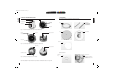
CMS 801 Manual 21-6-07AW 28/9/07 10:03 Page 3 C CMS 4. PRODUCT FEATURE IDENTIFICATION: Conduit/Cable Clamp M Y CM MY CY CMY K 5. ACCESSORIES: Each product is supplied with the following accessories as standard: Tuning Port Euro Type Connector Screws for mounting wings Mounting Wings C-Ring Tile bridge kit Note: A tile bridge kit must always be used when installing into suspended ceiling tiles Rotary Switch Fig 1.
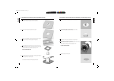
CMS 801 Manual 21-6-07AW 28/9/07 10:03 Page 4 C CMS 5.1 MECHANICAL INSTALLATION GUIDE FOR SUSPENDED CEILINGS M Y CM MY CY CMY K 5.2 MECHANICAL INSTALLATION GUIDE FOR SHEET-ROCK (PLASTER BOARD) CEILINGS 1 Remove the ceiling tile from its frame and place it on a flat surface. Mark the cut-out area on the ceiling tile by tracing around the template provided. 1 Mark the cut-out area on the ceiling by tracing around the template provided.
CMS 801 Manual 21-6-07AW 28/9/07 10:03 Page 5 C CMS 5.3 MECHANICAL INSTALLATION INSTRUCTIONS FOR OPTIONAL PLASTER RING: M Y CM MY CY CMY K 5.4 INSTRUCTIONS FOR OPTIONAL PRE-INSTALLATION BACK CAN (PI MODELS ONLY): An optional plaster (mud) ring bracket is available from Tannoy. This bracket is designed to be pre-installed into newly constructed, non-suspended ceilings. AN OPTIONAL PRE-INSTALL BACK CAN IS AVAILABLE FOR ALL PI (PRE-INSTALL) MODELS.
CMS 801 Manual 21-6-07AW 28/9/07 10:03 Page 6 C CMS 6. WIRING AND SETTING UP: 1 M Y CM MY CY CMY 7.1 CMS801 DC BM DIMENSIONS: TEMPLATE HOLE CUTOUT SIZE: 295mm Open the wiring cover at the back of the speaker can to access the Euro type connector plug and socket. 327.8 [12.90"] 310.5 [12.22"] 2 For connection to an amplifier, use pins 1 and 2: • Pin 1 is positive • Pin 2 is negative 5.0 [0.
CMS 801 Manual 21-6-07AW 28/9/07 10:03 Page 7 C CMS 7.4 CMS801 sub PI DIMENSIONS: M Y CM MY CY CMY K 8.1 TECHNICAL SPECIFICATIONS: MODEL TEMPLATE HOLE CUTOUT SIZE: 295mm CMS801 DC System 117.5 [4.63"] 286.4 [11.27"] 18.5 [0.73"] 325.0 [12.80"] Frequency response (-3dB) (1) BM back can 47Hz - 30kHz Frequency range (-10dB) (1) BM back can 40Hz - 35kHz Frequency range (-10dB) (1) PI back can 41Hz - 35kHz System sensitivity (1W @1m) (2) 92dB (1W = 2.
CMS 801 Manual 21-6-07AW 28/9/07 10:03 Page 8 C CMS 8.2 TECHNICAL SPECIFICATIONS: Frequency response (-3dB) Transducer Frequency range (-10dB) (1) 42Hz - 300Hz System sensitivity (1W @1m) Physical 92dB (1W = 2.45V for 8 Ohms) Enclosure Back can Baffle Integral 2nd order passive, Grille 160 Hz (2) Crossover Rated maximum SPL (2) 112dB (average) 118dB (peak) 110dB (average) With THP60 CM MY CY CMY K If desired, the grille and baffle panel may be painted to match the surrounding décor.
CMS 801 Manual 21-6-07AW 28/9/07 10:03 Page 9 C CMS 11. DECLARATION OF CONFORMITY: M Y CM MY CY CMY K NOTES The following apparatus is manufactured in China for Tannoy Ltd of Rosehall Industrial Estate, Coatbridge, Scotland, ML5 4TF and conform(s) to the protection requirements of the European Electromagnetic Compatibility Standards and Directives relevant to Domestic Electrical Equipment.
CMS 801 Manual 21-6-07AW 28/9/07 10:03 Page 10 C CMS 18 Composite NOTES M Y CM MY CY CMY K NOTES 19