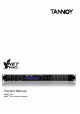
Owners Manual VNETTM SC1 * VNETTM SC1 (network enabled)
QUICK REFERENCE GUIDE DISPLAY The LCD displays preset and parameter information. The default screen is shown after start up and displays the number and name of the current preset on the lower line of text. When navigating around the adjustable parameters, other information is shown. CHANNEL SELECT BUTTONS The currently selected input or output channel is shown in the top left corner of the display. Pressing the channel select buttons scrolls through the available inputs and outputs.
CONTENTS 3. IMPORTANT SAFETY INSTRUCTIONS 5. PRODUCT FEATURE IDENTIFICATION 7. ACCESSORIES 8. HARDWARE OPERATION 16. SOFTWARE INSTALLATION 18. SOFTWARE OPERATION 24. PRODUCT DIMENSIONS 25. TECHNICAL SPECS 26. EQ AND FILTER RESPONSE GRAPHS 27. WARRANTY STATEMENT 29.
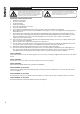
IMPORTANT SAFETY INFORMATION The lightning flash with an arrowhead symbol within an equilateral triangle, is intended to alert the user to the presence of uninsulated “dangerous voltage” within the product’s enclosure that may be of sufficient magnitude to constitute a risk of electric shock to persons. The exclamation point within an equilateral triangle is intended to alert the user to the presence of important operating and maintenance (servicing) instructions in the literature accompanying the product.
INSTALLATION INSTRUCTIONS 1 THIS PRODUCT MUST BE EARTHED. 2 Only use attachments and accessories approved by or specified by Tannoy. FOR CUSTOMERS IN EUROPE This product complies with both the LVD (electrical safety) 73/23/EEC and EMC (electromagnetic compatibility) 89/336/EEC directives issues by the commission of the European community.
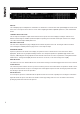
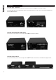
PRODUCT FEATURE IDENTIFICATION FRONT PANEL Store and Recall Buttons Input Signal Indicators Channel Select Buttons Edit Parameter Select Buttons Display Screen Limiter Indicator Parameter Edit Encoders Output Mute Buttons INPUT SIGNAL INDICATORS A set of three pairs of LEDs indicate signal present, +4dBu and input clip for each channel. The signal present LEDs operate at approximately –40 dBu, giving a useful indication of even relatively low input signal levels.
REAR PANEL OF STANDARD VNET SC1 Secure Mode Switch Blanking Plate Power Inlet Audio Output Connectors Serial Comms Port REAR PANEL OF NETWORK ENABLED VNET SC1 Audio Input Connectors VNETTM Network Port POWER INLET The Tannoy VNET SC1 unit should be connected to a suitable mains electricity supply using the cable supplied. The processor has a switch mode power supply that is capable of operating with a nominal mains voltage of 85V to 240V, 50/60Hz without re-configuration.
ACCESSORIES OPTIONAL VNETTM INTERFACE The rack-mountable VNet interface allows for communication between a VNETTM network and computer. If communicating with a non-networked SC1 direct communication via the PC & SC1 can be made with a standard serial lead, or USB-RS232 cable. OPTIONAL VNET INTERFACE POWER SUPPLY The PSU is only required when communication with a VNETTM network is by RS232.
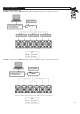
HARDWARE OPERATION CONNECTING THE VNETTM SC1 Example 1: Using a Tannoy VNETTM SC1 with a passive loudspeaker system (e.g. Tannoy V-SeriesTM) VNET TM SC1 * USB to Serial interface allows networking of multiple VNET speakers or SC1 controllers Example 2: Using a Tannoy VNETTM SC1 with a powered loudspeaker system (e.g.
Example 3: Using a network enabled VNETTM SC1 to combine an existing Tannoy VNETTM system with another loudspeaker system (e.g. Tannoy PowerV) VNETTM INTERFACE VNET TM SC1 * The VNETTM interface allows networking of multiple VNETTM speakers or SC1 controllers STARTING UP The unit will energise as soon as power is applied to the IEC inlet; there is no power switch.
NAVIGATION AND VIEWING PARAMETERS Many of the processing elements in each input and output path have features that may be controlled by the user, such as gain, frequency or limiter threshold. We call these adjustable features parameters. In A EQ1 Freq 100Hz Width 1.4Q Gain 0.0dB A parameter may be adjusted when it is displayed by turning one of the three-parameter knobs. Each of the three-parameter knobs is associated with a zone on the display.
PRESETS The device contains a total of forty-five user and Factory Presets. The user cannot overwrite the basic mono or basic stereo base presets. PRESET RECALL To select an existing preset, press the Recall Button so the indicator above it illuminates. Turn parameter knob A until the required preset number is shown on the display. Factory Presets are indicated by a box symbol appearing after the preset number. Press the Recall Button again to activate the Preset.
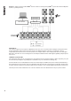
DSP PROCESSING INPUT DSP BLOCK DIAGRAM Input A Input LED’s Input Gain Delay 4th Order HPF Low Shelf EQ Six band PEQ High Shelf EQ Routing Sum - 6dB NB.
INPUT CHANNELS Gain Delay In A Gain 0.0dB In A Knob A: Gain, adjustable in 0.2dB steps from –80 dB to +20dB Delay 1.5ms Knob A: Delay, adjustable in variable steps from 0 to 400ms The delay parameter is adjustable in fine steps at low values; the adjustment becomes progressively coarser as the value increases. The velocity sensitive Parameter Knobs therefore provide accurate setting of driver offset delays (typically below 10ms) and rapid setting of longer system alignment delays.
OUTPUT CHANNELS Gain and Polarity Out1 Delay Gain 0.0dB Pol Rev Out1 Delay 1.50ms Knob A: Gain, adjustable in 0.2dB steps from –80 dB to +20dB Knob A: Gain, adjustable in 0.2dB steps from –80 dB to +20dB Knob B: Polarity, selectable, normal or reversed with reference to other outputs Knob B: Polarity, selectable, normal or reversed with reference to other outputs As for input delay, velocity sensitive Parameter Knobs provide finer adjustment at low levels and rapid selection of higher values.
UTILITIES Three utility functions are provided to adjust screen contrast, the display units used for parametric equalisation bandwidth and switch between stereo and mono mode. The device automatically adjusts for the variations in display contrast as the temperature of the LCD changes. The screen contrast utility control sets the base contrast of the screen and also allows optimization for a given viewing angle.
SOFTWARE INSTALLATION The enclosed disc contains the Podware software package; a comprehensive editor, interface, & diagnostics tool for the VNET™ range of products. Check the Tannoy website for any updates http://www.tannoy.com The disk should ‘AUTORUN’, if not open the ‘Podware’ folder & double click on the ‘Setup.exe’ icon. Your PC will need to have the Windows .NET Framework installed. If it does not, you will be directed to the necessary location to do so •http://msdn.microsoft.
INSTALLING THE SOFTWARE FROM THE CD 17 1. Exit all running programmes & insert the CD. Open the CD contents & Double click on the ‘Setup.exe icon. The welcome screen will appear. Click 2. Select your destination Folder. Click 3. Confirm Installation. Click 4. If you accept the licence agreement check ‘I Agree’ and Click 5. The programme will begin installing 6.
SOFTWARE OPERATION MENUS The menu system is arranged like so (FIG.
PodWare communicates with VNET™ using a serial ‘COM’ port as a ‘network’ connection. When a network connection is open and actively connected to a compatible device, the system is said to be ‘On Line’. Whilst On-line, you can control the connected device in ‘real time’, and continuously receive status information from the device. When going online, the application will take a few seconds while it copies the settings in the device to the control panel.
Controls have standardised properties that allow them to work in a consistent way across various control panels for different devices. Many controls will allow the mouse wheel to be used for fine adjustments, or the keyboard as an alternative (see Keyboard Shortcuts). When using the keyboard or the mouse wheel, it is necessary to have the control in question ‘in focus’. You can bring a control into focus either by tabbing to it (using the Tab key), or by clicking on it with the mouse.
DEVICE PROPERTIES At the top of the panel there are several pieces of information about the connected device (which are only activated when going On-line to a device): Model Name The model number (SC-1) Device name To uniquely identify the device (i.e. delay 3). This is set by the user.
The Low band has a low-pass crossover filter, and the High band has a high-pass and a low-pass crossover filter. A 2nd order low-shelf filter with frequency variable over the range 10Hz to 25kHz, and boost/cut from –15 to +15dB. A 2nd order high-shelf filter with frequency variable over the range 10Hz to 25kHz, and boost/cut from –15 to +15dB. Six bands of bell (parametric) equaliser, each band having frequency variable over the range 10Hz to 25kHz, bandwidth variable from 0.
UPDATING FIRMWARE Occasionally it may be necessary to update the devices firmware (with file extension .dfw); this may be due to added features or amendments to the VNET™ product. Check with your dealer/distributor or (www.tannoy.com) for any applicable updates. Firmware can be updated over the network (no need to disconnect speakers from the network) A firmware update will be common to all VNET™ products (one file for all models). Updating a devices firmware is straight forward:1. 2. 3.
PRODUCT DIMENSIONS 45mm (1.8") 482mm (19.0") 435mm (17.
TECHNICAL SPECIFICATIONS SYSTEM GENERAL Inputs Input Impedance Maximum Input level Outputs Output Impedance Maximum Output Level Sample Rate Bit Depth Frequency Response THD Dynamic Range Serial Comms Data PROCESSING Gain Output Ch. Source HP filter frequency LP filter frequency LP / HP filter type 2 > 10k Ohm Electronically balanced +20dBu 6 <100 Ohm, ground balanced +20dBu into 600ohm load 96kHz 24 bit 10Hz to 40kHz, +/- 3dB (filters disabled) 20Hz to 20kHz, +/- 0.5dB (filters disabled) <0.
EQ AND FILTER RESPONSE GRAPHS Linkwitz-Riley 6 0 0 -6 Magnitude,dB Magnitude,dB Butterworth 6 -12 -18 -24 -30 -36 -6 -12 -18 -24 -30 1-103 100 -36 1-104 1-103 100 Frequency, Hz 6dB/Oct 12dB/Oct 24dB/Oct 48dB/Oct 12B/Oct 18dB/Oct 0 0 -6 -6 Magnitude,dB Magnitude,dB 48dB/Oct 6 -12 -18 -24 -30 -12 -18 -24 -30 1-103 100 -36 1-104 1-103 100 Frequency, Hz 6dB/Oct 1-104 Frequency, Hz 4th Order 12dB/Oct 8th Order Butterworth Shelving EQ 15 15 10 10 Magnitude,dB Magni
WARRANTY No maintenance of the VNETTM SC1 device loudspeakers is necessary. As part of the MUSIC Group, Tannoy is committed to providing the highest quality products, service and user experience for our customers. One element of this commitment is our after sales support which now incorporates our extended Limited Warranty. In the event of any concern that is not addressed by this extended Limited Warranty we would ask you to contact us at care@music-group.
NOTES 28
NOTES 29
NOTES 30
REVISION DATE: 23rd November 2015 6481 0507 Tannoy operates a policy of continuous research and development. The introduction of new materials or manufacturing methods will always equal or exceed the published specifications. All specifications are subject to change without notice. Copyright (c) 2015 Music Group Innovation SC Ltd. All rights reserved.