CHANNEL 1 GATE -50 -30 -70 CHANNEL 2 COMPRESSOR / LIMITER -15 -20 -10 0 2 2.5 +10 0 -30 10 5 50 100 0.3 0.5 AIR 0 +10 -40 +20 1 LIM 0.1 200 dBu n:1 ms THRESHOLD RATIO ATTACK dBu +14 3 -20 +20 sec dB RELEASE OUTPUT IN/OUT 15 10 6 4 2 AC 100-120V, 60Hz AC 200-240V, 50HZ RATED INPUT: 12.5W CH 2 OFF FULL AUTO CH 1 IN AUTO CH 2 IN/OUT GATE -50 -30 COMPRESSOR / LIMITER -15 -20 -10 0 2.
CAUTION AVIS RISK OF ELECTRIC SHOCK DO NOT OPEN RISQUE DE CHOC ELECTRIQUE NE PAS OUVRIR CAUTION: TO REDUCE THE RISK OF ELECTRIC SHOCK DO NOT REMOVE COVER (OR BACK) NO USER-SERVICEABLE PARTS INSIDE REFER SERVICING TO QUALIFIED PERSONNEL ATTENTION: POUR EVITER LES RISQUES DE CHOC ELECTRIQUE, NE PAS ENLEVER LE COUVERCLE. AUCUN ENTRETIEN DE PIECES INTERIEURES PAR L'USAGER. CONFIER L'ENTRETIEN AU PERSONNEL QUALIFIE.
18. Exposure to extremely high noise levels may cause permanent hearing loss. Individuals vary considerably in susceptibility to noise-induced hearing loss, but nearly everyone will lose some hearing if exposed to sufficiently intense noise for a period of time. The U.S. Government’s Occupational Safety and Health Administration (OSHA) has specified the permissible noise level exposures shown in the following chart.
Getting Started The following steps will help you set up your SQ•2, and get the levels just right. SETTINGS: SET THE CONTROLS: 1. Be sure the SQ•2’s POWER switch is off. 1. Make sure your signal source is turned up and delivering signal to the SQ•2. The signal should pass through the SQ•2 unaffected because the CHAN 1 and 2 IN/OUT buttons are out and the signal processing circuitry is bypassed. 2. Turn all the controls to their center positions (12 o’clock) and set all the switches out. CONNECTIONS: 1.
Contents Safety Instructions................................................................2 Getting Started ....................................................................4 Introduction..........................................................................6 Hookup Diagrams................................................................8 Typical Hookup: In-line with Main Outputs.....................8 Alternate Hookup: Individual Channel or Main Inserts ..8 SQ•2 Features ............................
Introduction Thank you for choosing a TAPCO® Squeez™ dynamics processor by Mackie®. The TAPCO product line hails back to the days of TAPCO Corporation, Greg Mackie’s first company. TAPCO revolutionized the audio industry back in 1969 with the very first 6-channel mixer specifically designed for keyboards and rock ‘N’ roll PA. In essence, TAPCO redefined the price performance ratio and made high-quality professional audio mixers accessible to virtually anyone.
The Gate/Expander Typically, a gate is used to turn off a channel when there is no signal to reduce the overall noise level of the mix. When the signal drops below a certain level determined by the threshold control, it is turned off. When the signal comes back up and crosses the threshold, the level returns to normal.
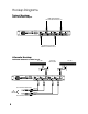
Hookup Diagrams Typical Hookup: In-line with Main Outputs FROM MIXING CONSOLE LEFT AND RIGHT MAIN OUTPUTS AC~120V/60Hz SERIAL / DATE CODE OUTPUT INPUT BAL/ UNBAL AC FUSE T 0.315A BAL/ UNBAL SIDE CHAIN OUTPUT = INPUT TIP RING = OUTPUT SLEEVE = GROUND BAL/ UNBAL INPUT BAL/ UNBAL SIDE CHAIN = INPUT TIP RING = OUTPUT SLEEVE = GROUND WWW.TAPCOGEAR.
SQ•2 Features 3 GATE 1 -50 -30 -70 -15 -20 4 0 2 2.5 6 8 50 0.5 0 CHANNEL 1 5 10 100 0.3 -6 1 10 AIR +10 -40 dBu +20 dBu 1 LIM n:1 0.1 200 THRESHOLD 2 RATIO 50ms ms CLOSE THRESHOLD 12 CHANNEL 2 20 15 10 6 4 2 GATE 1 -50 +6 2 -14 150 0.1 81 +14 -30 3 sec -20 CH 1 +20 OFF IN/OUT RELEASE AUTO -15 -20 -10 AUTO 0 OUTPUT 2 2.5 5 +10 0 -30 10 50 100 IN OFF +10 -40 +20 -6 1 0 +6 2 -14 150 0.1 81 dBu ON +14 BY 1 LIM n:1 0.
3 GATE 1 -50 -30 2 0 6 50 0.5 CHANNEL 1 2.5 5 10 100 0.3 10 8 -6 +10 -40 +20 1 dBu dBu THRESHOLD 2 20 15 10 6 4 2 -50 LIM 0.1 200 ms n:1 RATIO 50ms 3 +14 sec -20 -30 OFF -20 -10 IN/OUT RELEASE AUTO OUTPUT LEVEL IN OFF +10 -40 +20 dBu THRESHOLD 11. GAIN REDUCTION Meters These 8-segment meters indicate the amount of gain reduction that is applied to the signal by the compressor. It ranges from 1 to 30 dB of gain reduction.
15. OUTPUT Two types of connectors are provided for the outputs — male XLR and 1/4” TRS (Tip-Ring-Sleeve). These balanced outputs are in parallel, and provide exactly the same signal. You can connect either a balanced TRS connector or an unbalanced TS connector to the 1/4” output jack. See “Appendix B: Connections” on page 14 for information on output connection wiring. 16. INPUT Two types of connectors are provided for the inputs — female XLR and 1/4” TRS (Tip-Ring-Sleeve).
Appendix A: Service Information Warranty Service No Sound Details concerning Warranty Service are spelled out in the Warranty section on page 19. If you think your SQ•2 has a problem, please do everything you can to confirm it before calling for service. Doing so might save you from the deprivation of your compressor and the associated suffering. These may sound obvious to you, but here are some things you can check. Read on.
Repair Service for TAPCO products is available from one of our authorized domestic service centers or at our factory, located in sunny Woodinville, Washington. Service for TAPCO products living outside the United States can be obtained through local dealers or distributors. If your SQ•2 needs service, follow these instructions: 1. Review the preceding troubleshooting suggestions. Please. 2.
Appendix B: Connections XLR Connectors 1/4" TS Phone Plugs and Jacks The inputs and outputs use 3-pin male and female XLR connectors. They are wired as follows, according to standards specified by the AES (Audio Engineering Society). “TS” stands for Tip-Sleeve, the two connection points available on a mono 1/4" phone jack or plug. They are used for unbalanced signals.
Appendix C: Technical Info SQ•2 Specifications Frequency Response 20 Hz to 20 kHz (+0, –1 dB) Audio Input Type: Active balanced XLR and 1/4" jacks Impedance: 60 kΩ balanced Maximum Input Level: +21 dBu balanced and unbalanced Audio Output Type: XLR and 1/4" jacks Impedance: <40 kΩ unbalanced Maximum Output Level: +21 dBu THD+N @ 1 kHz, +4 dBu: 0.05% typical SMPTE IMD, +4 dBu: 0.
2 BALANCED LINE INPUT 1 3 (XLR-F) 17 FUSE TAPCO SQ•2 BLOCK DIAGRAM 12.30.
1 dBu -30 -20 dBu -10 3 +20 13 2 2 CHANNEL 1 5 6 RATIO n:1 2.5 LIM 5 0.1 81 AC FUSE T 0.315A ms 50 0.3 -6 dB 0 +14 +20 +6 14 7 9 SERIAL / DATE CODE OUTPUT LEVEL BROUGHT TO YOU BY THE GROOVY FOLKS IN WOODINVILLE, WA, USA "TAPCO" AND "MACKIE" ARE REGISTERED TRADEMARKS OF LOUD TECHNOLOGIES INC. • COPYRIGHT ©2003 WWW.TAPCOGEAR.
by 18
TAPCO LIMITED WARRANTY A. LOUD Technologies Inc. warrants all materials, workmanship and proper operation of this TAPCO product for a period of one year from the original date of purchase. If any defects are found in the materials or workmanship, or if the product fails to function properly during the applicable warranty period, LOUD Technologies, at its option, will repair or replace the product. This warranty applies only to equipment sold and delivered within the U.S.
tapcogear.