Operation Drywall Feed Pump 3A0245A ENG U.S. Patents Pending: 61/315,288; 61/315/322; 61/316,013; 61/316,010 - For water-based materials only - Not for use in explosive atmospheres - Not for use with quick-set materials READ ALL WARNINGS AND INSTRUCTIONS Read all warnings and instructions in this manual. Save these instructions. Maximum Working Pressure 2500 psi (17.
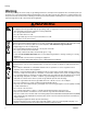
Warning Warning The following warnings are for the setup, use, grounding, maintenance, and repair of this equipment. The exclamation point symbol alerts you to a general warning and the hazard symbols refer to procedure-specific risks. When these symbols appear in the body of this manual, refer back to these Warnings. Product-specific hazard symbols and warnings not covered in this section may appear throughout the body of this manual where applicable.
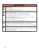
Warning WARNING WARNING MOVING PARTS HAZARD Moving parts can pinch, cut or amputate fingers and other body parts. • Keep clear of moving parts. • Do not operate equipment with protective guards or covers removed. • Pressurized equipment can start without warning. Before checking, moving, or servicing equipment, follow the Pressure Relief Procedure and disconnect all power sources. EQUIPMENT MISUSE HAZARD Misuse can cause death or serious injury.
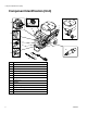
Component Identification (Unit) Component Identification (Unit) K H A J P G L B M C E ti14874a N D F 4 A Pump Module B Prime/Tool Fill/Recirculation Valve/Pressure Relief C Flow Control Knob D ON/OFF Switch E 15/20 Amp Switch (North America only) F Material Hoses G Movable Handle H Pump Connector J Prime Hose K Hopper L Hopper Plug M Expandable Plug N Pump P Material Screen 3A0245A
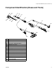
Component Identification (Hoses and Tools) Component Identification (Hoses and Tools) AA BB FF GG HH JJ CC DD PP EE NN RR LL ti15676a MM KK AA Fluid Manifold BB Fluid Outlet CC Fluid Inlet DD Hose 1/2 in. x 50 ft (max 150 ft) EE Fitting 1/2 in. x 1/4 in. FF Hose 1/4 in.
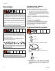
Grounding Grounding GROUNDING INSTRUCTIONS (North America) This appliance is rated more than 15 A and is for use on a circuit having a nominal rating of 120 V and is factory equipped with a specific electric cord and plug. No adapter should be used with this appliance. If the appliance must be reconnected for use on a different type of electric circuit, the connection should be made by qualified service personnel; and after the connection, the appliance should comply with all local codes and ordinances.
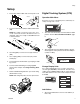
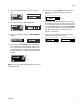
Setup Setup 1. Turn power switch to OFF and connect power cord. Digital Tracking System (DTS) ti4265a ti2810a Operation Main Menu Short press to move to next display. Press and hold (5 seconds) to change units or reset. ti4265a 2. Connect material hose (DD) to fluid manifold outlet (BB). NOTE: Up to 150 ft of 1/2 in. plus 15 ft. x 1/4 in. hose can be connected to the unit. If desired flow rate is not obtainable, reduce hose length or add additional water to material mixture. BB ti13605a 1.
Setup Psi ti13667a ti13612a ti13620a ti13610a NOTE: You must be facing the unit and be no more than 10 ft away to learn the controller. The unit can only be operated by one learned controller at a time. NOTE: JOB scrolls past, then the number of gallons dispensed displays. Secondary Menu - Stored Data 2. Press and hold to reset to zero. 1. Perform Pressure Relief Procedure, see page 6. Lifetime Gallons 1. Short press DTS button to move to LIFE gallons (or liters x 10).
Setup 6. Press and hold DTS button to clear error code to zero. 10. Short press to enter CLEAR mode. Hold in DTS button to clear all RF signals that were being blocked. ti15693a ti13614a ti13608a 7. Short press to move to SOFTWARE REV. ti13623a ti13613a 8. Short press to display number of GUN TRIGGERS logged. 11. Short press to RF ON/OFF mode (this is used for Troubleshooting only). To turn RF off and enter pressure control mode, make sure flow control knob is at zero.
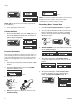
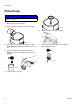
Prime Pump Prime Pump NOTICE Do not use with quick-set materials. They can harden inside the unit and hose. 1. Mix material in separate bucket. 2. Add 1-2 gallons (4-8 liters) of material to hopper. ti15746a 6. Add the remaining material to hopper. ti15747a ti11670a 3. Place prime hose deflector into hopper or empty bucket. NOTE: Keep deflector shield wet once it is in use. 7. After unit is primed, turn prime valve handle to APPLY FINISH position. 4.
Using Finishing Tools Using Finishing Tools 3. Use flow control knob (C) to set material flow rate. Turn flow control knob clockwise to increase material flow. Corner Finishing ti8794a C ti15681a 1. Attach corner finisher inlet swivel to inline valve controller (JJ) valve using quick-connect clamp (QC) attached to valve. NOTE: Fine flow rate adjustments can be made using “+” and “-” buttons on inline valve controller. Flow rate can only be adjusted relative to position of flow control knob.
Using Finishing Tools Flat Box Finishing 5. Place flat box at end of joint. 6. Pull trigger and lead with handle and draw the tool along the joint. 7. Near middle of the joint, remove flat box from joint surface by applying brake and using a sweeping motion. ti15676a 8. Adjust hand position and begin again at other end of joint. 1. Attach male inlet of box finisher to the Z-swivel assembly using quick-connect clamp attached to Z-swivel. 2.
Using Finishing Tools Automatic Taping 1. Remove creaser wheel trigger pin. 5. Use flow control knob (C) to set material flow rate. Turn flow control knob clockwise to increase material flow. ti15679a ti8794a C 2. Attach taper tool to inline valve. NOTE: Fine flow rate adjustments can be made using “+” and “-” buttons on inline valve controller. Flow rate can only be adjusted relative to position of flow control knob. The fine flow rate can only go down from, and up to the flow control knob setting.
Storage Storage 3. Remove remaining material from hopper. 4. Turn pump control fully counter-clockwise to shut pump off. NOTICE Do not use with quick-set materials. They can harden inside the unit and hose. ti8793a 1. Perform Pressure Relief Procedure, page 6 (prime valve handle in down position). Leave prime valve handle in PRESSURE RELIEF position. 5. Fill material hopper with water and run pump to flush unit. Run water through material hose, tools and drain line thoroughly flush system.
Troubleshooting Troubleshooting Motor Will Not Operate (See flow chart, page 25) PROBLEM Basic fluid flow problems CAUSE Flow control knob turned up but unit is not pumping. SOLUTION Learn the Controller, see page 9. Check battery voltage. Flow control knob setting. Motor will not run if Slowly increase flow setting to see if at minimum setting (fully counterclockwise). motor starts. Basic mechanical problems Basic electrical problems Valve or filter may be clogged. Relieve pressure and clear clog.
Troubleshooting Low or Fluctuating Output PROBLEM Low output CAUSE SOLUTION Pump is worn or clogged. Service pump. Check piston and intake valves for wear or obstructions. Material hose length. Longer hose length reduces drywall feed pump performance. Reduce hose length or thin material. Use 20A setting if available. Pump hopper adapter connections are loose. Tighten any loose connections. Replace pump hopper adapter if cracked or punctured.
Troubleshooting Low or Fluctuating Output (continued) PROBLEM Motor runs and pump strokes CAUSE SOLUTION No material supply. Refill hopper and re-prime pump. Clean hopper strainer. Loose fittings. Tighten; use thread sealant or sealing tape on threads if necessary. Intake valve ball and piston ball are not seating properly. Remove intake and piston valves and clean. Check balls and seats for nicks or obstructions; replace if necessary, page 18.
Troubleshooting RF Problems PROBLEM CAUSE SOLUTION Unwanted signal will not allow unit Unwanted RF signal. Undesired controller is Stop unwanted RF signal by deactivatto learn the controller. active and in close proximity. ing the controller. Use BLOCK feature on Secondary Menu, see page 8. RF controller will not learn. Interference in RF signal 18 Battery is depleted. Replace battery (CR123A Lithium 3V). Unit has not learned the controller. Learn the controller, see page 8.
Troubleshooting Electrical Problems Symptom: Unit does not run or stops running. Perform Pressure Relief Procedure; page 6. • Plug unit into correct voltage, grounded outlet • Set power switch OFF for 45 seconds and then ON again (this ensures drywall feed pump is in default flow control mode).
Troubleshooting TYPE OF PROBLEM Drywall feed pump does not run at all Digital display shows E=03 Control board status light blinks 3 times repeatedly 20 WHAT TO CHECK Check transducer or transducer connections (control board is not detecting a pressure signal). HOW TO CHECK 1. Turn unit OFF and disconnect power. 2. Check transducer and connections to control board. 3. Disconnect transducer from control board socket. Check to see if transducer and control board contacts are clean and secure. 4.
Troubleshooting TYPE OF PROBLEM Drywall feed pump does not run at all Digital display shows E=05 WHAT TO CHECK HOW TO CHECK 1. Control is commanding motor to run but motor shaft does not rotate. Possibly locked rotor condition, an open connection exists between motor and control, there 2. is a problem with motor or control board. 3. Control board status light blinks 5 times repeatedly Remove pump pin and try to run unit. If motor runs, check for locked or frozen pump or drive train.
Troubleshooting TYPE OF PROBLEM Drywall feed pump does not run at all Digital display shows E=05 Control board status light blinks 5 times repeatedly WHAT TO CHECK 6. Control is commanding motor to run but motor shaft does not rotate. Possibly locked rotor condition, an open connection exists between motor and control, there is a problem with motor or control 7. board, or motor amp draw is excessive. HOW TO CHECK Perform Field Short Test: Test at large 4-pin motor field connector.
Troubleshooting TYPE OF PROBLEM Drywall feed pump does not run at all WHAT TO CHECK Is motor overheating? Digital display shows E=06 Control board status light blinks 6 times repeatedly HOW TO CHECK NOTE: Motor must be cooled down for the test. 1. Allow unit to cool. If unit runs when cool, correct cause of overheating. Keep unit in cooler location with good ventilation. If unit still does not run, follow Step 1. 2. Check fan and air intake. 3. Check motor thermal switch. 4.
Troubleshooting Unit Will Not Shut Off Perform Pressure Relief Procedure; page 6. Leave prime valve handle open and power switch OFF. Troubleshooting Procedure: Is the prime valve handle in the Prime/Tool Fill/Recirculation position? Turn prime valve handle to Apply Finish position and turn unit ON. Does the unit shut off? YES END YES END YES END NO Is the inline valve controller or box slide controller triggered? If so, detrigger the controller.
Troubleshooting Unit Will Not Run (See following page for steps) Turn unit ON. Error Code Displayed See Error Code section for further troubleshooting See Step 1. Do you have over 100 AC volts (200 for 230V units)? NO See Step 2. Do you have over 100 AC volts (200 AC volts for 230V units? NO Repair or replace power cord. YES Replace the ON/OFF switch. YES See Step 3. Is the proper reading present through the thermal switch wires? NO If motor is hot, let cool and retest.
Troubleshooting Unit Will Not Run - Steps: 100-120 VAC NA Units STEP 2: V - 110-120 AC Plug power cord in and turn switch ON. Connect wires to control board and ON/OFF switch. Turn meter to AC volts. V - STEP 3: Black Power Cord Black White Control Board Thermal Switch + On/Off Switch + Black - Thermal Switch Black On/Off Switch 100k ohm Plug power cord in and turn switch ON. Connect wires to control board and ON/OFF switch. Turn meter to AC volts.
Troubleshooting Unit Will Not Run - Steps: 100-120 VAC UK STEP 2: V - Plug power cord in and turn switch ON. Connect wires to control board and ON/OFF switch. Turn meter to AC volts. Black White On/Off Switch Brown 110-120 AC V - Black On/Off Switch Brown + STEP 3: 100k ohm Plug power cord in and turn switch ON. Connect wires to control board and ON/OFF switch. Turn meter to AC volts. - Thermal Switch White Check motor thermistor. Unplug yellow wires. Meter should read 6.2k ohms.
Troubleshooting Unit Will Not Run - Steps: 220-240 VAC Units V Black STEP 2: STEP 1: 220-240 VAC Plug power cord in and turn switch ON. Connect wires to ON/OFF switch. Turn meter to AC volts. V Black White STEP 3: White Blue On/Off Switch Blue On/Off Switch - Thermal Switch Brown Brown 100k ohm Plug power cord in and turn switch ON. Connect wires to ON/OFF switch. Turn meter to AC volts. Check motor thermistor. Unplug yellow wires. Meter should read 6.2k ohms.
Technical Data (Unit) Technical Data (Unit) Power requirements: Models 257100, 262288 Models 258906, 262300 Model 258907 Motor HP (W) Maximum fluid working pressure Hopper capacity Maximum delivery with texture material Maximum hose length Fluid outlet size Dimensions Length Width Height Weight (with hoses and applicator) Wetted parts 100-120 VAC, 60 Hz, 15/20A 220-240 VAC, 50 Hz, 10A 100-120 VAC, 50/60 Hz, 15A 2.5 (1864) 2500 psi (17.2 MPa, 172 bar) 25 gallons (95 liters) Up to 1.5 gpm (5.
Notes Notes 30 3A0245A
Graco Standard Warranty Graco Standard Warranty Graco warrants all equipment referenced in this document which is manufactured by Graco and bearing its name to be free from defects in material and workmanship on the date of sale to the original purchaser for use. With the exception of any special, extended, or limited warranty published by Graco, Graco will, for a period of twelve months from the date of sale, repair or replace any part of the equipment determined by Graco to be defective.
All written and visual data contained in this document reflects the latest product information available at the time of publication. Graco reserves the right to make changes at any time without notice. Original instructions. This manual contains English. MM 3A0245 Graco Headquarters: Minneapolis International Offices: Belgium, China, Japan, Korea GRACO INC. P.O. BOX 1441 MINNEAPOLIS, MN 55440-1441 Copyright 2010, Graco Inc. is registered to ISO 9001 www.graco.