Repair Pump for Drywall Feed Pump System - For water-based materials only - Not for use in explosive atmospheres - Not for use with quick-set materials READ ALL WARNINGS AND INSTRUCTIONS Read all warnings and instructions in this manual. Save these instructions. Maximum Working Pressure 2500 psi (17.
Warning Warning The following warnings are for the setup, use, grounding, maintenance, and repair of this equipment. The exclamation point symbol alerts you to a general warning and the hazard symbols refer to procedure-specific risks. When these symbols appear in the body of this manual, refer back to these Warnings. Product-specific hazard symbols and warnings not covered in this section may appear throughout the body of this manual where applicable.
Warning WARNING WARNING MOVING PARTS HAZARD Moving parts can pinch, cut or amputate fingers and other body parts. • Keep clear of moving parts. • Do not operate equipment with protective guards or covers removed. • Pressurized equipment can start without warning. Before checking, moving, or servicing equipment, follow the Pressure Relief Procedure and disconnect all power sources. EQUIPMENT MISUSE HAZARD Misuse can cause death or serious injury.
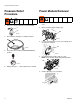
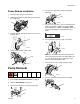
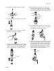
Pressure Relief Procedure Pressure Relief Procedure Power Module Removal 1. Turn flow control knob to fully counterclockwise. 1. Perform Pressure Relief Procedure. Unplug power cord. 2. Release hopper adapter clamp (158). 158 ti8793a 2. Place deflector in hopper or suitable container. ti15684a 3. Loosen rod clamp knob (112) on front of pump module and push rod down. 112 ti14876a 3. Turn prime valve handle to PRESSURE RELIEF position. ti11675a 4. Lift and pull power module (153) off of unit.
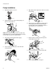
Pump Removal Power Module Installation 4. Loosen two screws (40) and remove pump rod shield (48). 1. Remove hopper plug (117) if installed. 40 48 2. Replace power (153) module and insert pump outlet into hopper inlet. 153 ti15619a 5. Turn flow control knob to a very low setting and turn prime valve handle to TOOL FILL position (JOG mode will appear in display). Use ON/OFF switch or turn control knob OFF to stop pump when pin is visible. ti15625a 3.
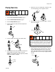
Pump Removal Pump Installation 1. Extend pump piston rod 1.5 in. 5. Align pump outlet to right side so that hose can be reassembled. 1.5 in. ti7171a 2. Install pump pin (7b). Verify retaining spring is in groove of connecting rod. ti15923a 6. Screw jam nut up toward drive housing until nut stops. Tighten jam nut by hand, then tap 1/8 to 1/4 turn with a 20 oz. (maximum) hammer to approximately 75± 5 ft-lb (102 N•m). 7b ti13093a NOTE: Pin should be installed from the top side of the pump.
Pump Service Pump Service 7. Tap piston rod out of cylinder with a hammer or flip over and tap piston rod out against a bench. Disassemble the Pump 1. Perform Pressure Relief Procedure, page 4. 2. Perform Power Module Removal, page 4. 3. Perform Pump Removal, page 5. 8. Remove piston (311) from sleeve (306), or remove sleeve from cylinder. 4. Remove packing nut (312) and throat adjustment spacer (302). 312 311 306 5. Unscrew intake valve (319) from cylinder (304). 304 319 6.
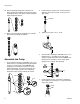
Pump Service 10. Remove packings and glands from piston rod. Discard packings and glands. Remove piston wiper and back-up washer from piston rod. Discard piston wiper and back-up washer. 2. Install ball (315c) in piston rod. If thread sealant is applied to piston valve threads, ensure that none gets on ball. 315c 11. Remove throat packings and glands from cylinder. Discard throat packings and glands. Assemble the Pump 1. Soak all leather packings in SAE 30W oil for 1 hour minimum prior to assembly.
Pump Service 6. Grease piston packings and sleeve top edge. 10. Reassemble intake valve with new o-ring (315a), seat (309a) and ball (315b). Seat may be flipped over and used on other side. Clean seat thoroughly. Place intake spring (315r) on top of ball guide (317). 317r 317 315b 309a 315a 7. Carefully slide piston assembly into top of sleeve. 11. Install intake valve on cylinder. If a wrench is used, torque to 200 +/- 15 ft-lb. If a wrench is not used, be sure intake valve is tight against cylinder.
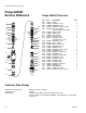
Pump 24E957 Service Reference Pump 24E957 Service Reference Pump 24E957 Parts List 301 312 315k 302 325 315g 315j 315q 315f 315g 315j Ref.
Notes Notes 3A0912A 11
Graco Standard Warranty Graco warrants all equipment referenced in this document which is manufactured by Graco and bearing its name to be free from defects in material and workmanship on the date of sale to the original purchaser for use. With the exception of any special, extended, or limited warranty published by Graco, Graco will, for a period of twelve months from the date of sale, repair or replace any part of the equipment determined by Graco to be defective.