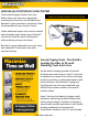
OPERATION MANUAL
BAZOOKA® CONTINUOUS FLOW SYSTEM Finish drywall projects faster than ever before when you keep your taping tool continuously at work on the wall while the Bazooka® system provides a continuous flow of compound into your choice of tools. A HIGH-VOLUME PRODUCTIVITY SYSTEM Unlike traditional tapers that must be loaded and reloaded using a hand pump, Bazooka® Continuous Flow can work continuously without having to stop and reload.
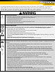
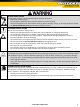
The following warnings are for the setup, use, grounding, maintenance and repair of this equipment. The exclamation point symbol alters you to a general warning and the hazard symbols refer to procedure-specific risks. When these symbols appear in the body of this manual, refer back to these Warnings. Product-specific hazard symbols and warnings not covered in this section may appear throughout the body of this manual where applicable. ELECTRIC SHOCK HAZARD This equipment must be grounded.
MOVING PARTS HAZARD Moving parts can pinch, cut or amputate fingers and other body parts. • Keep clear of moving parts. • Do not operate equipment with protective guards and covers removed. • Pressurized equipment can start without warning. Before checking, moving, or servicing equipment, follow the Pressure Relief Procedure and disconnect all power sources. EQUIPMENT MISUSE HAZARD Misuse can cause death or serious injury.
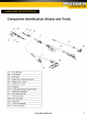
COMPONENT IDENTIFICATION © 2011 AMES TAPING TOOLS 4
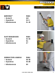
USING FINISHING TOOLS BAZOOKA® • General • Operation • Maintenance PAGE 6-8 9-11 11-12 FLAT FINISHER BOX • General • Operation • Maintenance PAGE 13-15 16 17 CORNER TOOL HANDLE • General • Operation • Maintenance PAGE 18-19 19-20 20 © 2011 AMES TAPING TOOLS 5
BAZOOKA® The taping process using the Bazooka® Continuous Flow Taper. There are three important facts you should remember about the Bazooka® Continuous Flow Taper: • Current automatic taper users can move up to Bazooka® Continuous Flow with minimal training – the tools are almost identical! • It simultaneously applies tape and joint compound to any wall joint and will cut the tape to the desired length.
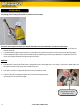
BAZOOKA® (cont’d) 4. Align the valve so that the trigger lines up with the tape spool. Secure by tightening the clamp nut. 5. The creaser trigger is attached to the valve using the clevis pin. 6. The range of the creaser trigger may be adjusted by threading the nut in or out. 7. The hose can now be connected to the open end of the valve, similar to the way that the valve was attached to the taper. 8.
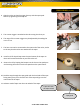
BAZOOKA® (cont’d) 12. The taper is operated by placing one hand on the inline mechanical valve, controlling the compound flow, and the other hand on the taper control tube, controlling tape advancing and cutting. 13. Normally, the control tube is held at the top most end of its stroke during taper operation. 14. The spring loaded creaser wheel may also be retracted temporarily by operating the creaser trigger with the hand on the inline mechanical valve. 15.
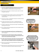
BAZOOKA® (cont’d) TAPER OPERATION: 1. Generally you will start by taping butt joints first, followed by flat joints and finally inside angle joints. 2. You will need to position the end of the exposed tab of tape at the beginning of the joint to be taped. This may be done by advancing the tape one time and manipulating the creaser wheel to retract it (either with pressure against the adjoining wall or floor, or by using the creaser trigger). 3.
BAZOOKA® (cont’d) HORIZONTAL JOINTS: 1. To tape horizontal joints, place the tab of tape at the beginning of the joint to be taped. Squeeze the valve lever fully as you begin to move the head of the taper along the joint. 2. Lead with the head of the taper as soon as is practical to make tracking easier. 3. When the head of the taper is about 2-1/2” from the end of the joint, release the valve lever as you stop moving the taper. 4.
BAZOOKA® (cont’d) INSIDE ANGLES (cont’d): 4. For best operation, avoid “twisting” the taper as you track the joint and lead with the head of the taper as soon as is practical. This will minimize “creeping” of the tape along the joint. MAINTENANCE: 1. This tool must be thoroughly washed after each use. Flush the compound from the tool with water, either with the pump or with a water hose and cleaning adapter. 2.
BAZOOKA® (cont’d) GOOSER NEEDLE REPLACEMENT: 1. The gooser needle is sharp and should always be handled with pliers. 2. While holding the pin that extends out of the needle holder, loosen the clamp screw and remove the existing gooser needle with a pair of pliers. 3. Insert some tape in the tape guide and then install the new needle using a pair of pliers. 4. Gently press the needle into the tape so that the point slightly protrudes through the other side of the tape and tighten the clamping screw.
FLAT FINISHER BOX The finishing process using the Bazooka® Continuous Flow Flat Finisher Box and Handle. There are three important facts you should remember about the Bazooka® Continuous Flow Flat Finisher Box and Handle: • The learning curve is minimized because the brake and box operation is almost identical to a traditional Ames® box and handle. • The teardrop shape of the handle makes it very comfortable and easy to use.
FLAT FINISHER BOX (cont’d) 7. After selecting the proper width box and length of handle for the job, the operator connects them by threading the box studs into the wingnuts on the handle connector plate. 8. The wingnuts should be tightened snuggly by hand, but no tools need to be used to provide a secure connection. No tools needed to tighten wingnuts 9. The hose is then connected by inserting the quick disconnect pilot fitting of the hose into the grip end of the handle.
FLAT FINISHER BOX (cont’d) 11. The box slide controller is then wrapped around the handle with the extended portion of the transmitter closest to the brake lever grip. 12. The box slide controller should securely snap in place over the shape of the handle and can either be locked into place or allowed to slide freely by adjusting the locking nut on the top side. The box slide controller brake allows the controller to be positioned on the handle 13.
FLAT FINISHER BOX (cont’d) BOX OPERATION: 1. The Ames® Continuous Flow Flat Finishers can be used in a variety of ways. It’s possible to use these boxes very much like traditional ATF flat finishers by using the pump between joints to keep the boxes supplied with compound. 2. It’s also possible to use the pump only when the boxes are on the wall to actually help push the material out of the box. Or any combination of the above may be used as well. BEGIN FLATS: 1.
FLAT FINISHER BOX (cont’d) MAINTENANCE: 1. This tool must be thoroughly washed after each use. Flush the compound from the tool with water, either with the pump or with a water hose and cleaning adapter. 2. External material can be sprayed off with a hose or removed with a cleaning brush. 3. After cleaning, lightly lubricate all moving parts with Ames® Bazooka® Oil. BOX BLADE REPLACEMENT: 1.
CORNER TOOL HANDLE The finishing process using the Bazooka® Continuous Flow Corner Tool Handle. There are three important facts you should remember about the Bazooka® Continuous Flow Corner Tool Handle: • It eliminates lap marks because you only have to move along the joint in one direction. • It uses heaver joint compound, therefore there is less shrinkage and better coverage over the tape.
CORNER TOOL HANDLE (cont’d) 5. Secure by tightening the clamping nut. 6. The hose can now be connected to the open end of the valve, similar to the way that the valve was attached to the handle. 7. The corner tool can now be installed over the end of the handle outlet ball. 8. The flow of material from the pump through the handle is actuated by fully squeezing the valve lever. Compound will flow through the hose, through the handle out of the ball outlet. 9.
CORNER TOOL HANDLE (cont’d) BEGIN ANGLES: 1. Fully squeeze the valve lever to start the flow of compound and move the tool toward the other end of the joint. 2. Release the valve lever to stop the flow of compound about 3-6” from the end of the joint. 3. Repeat for the next joint to be finished. TRAINING NOTE: For horizontal angles, you can run the joint around the entire room in the same direction. For vertical angles, you should start at the floor and run the joint in one sweep to the very top.
TROUBLESHOOTING TIPS UNIT AND PUMP* 1. Low mud flow • Check amp switch. It is always better when possible to run the pump on 20 amp rather than 15. • You should not use less than 12G cord and no longer than 200’. • Compound consistency is important; the thicker the material the slower the compound flow. • Make sure pump has been properly primed (always when filling the hopper for the first time, put a small amount of joint compound under the filter screen to start suction).
TROUBLESHOOTING TIPS (cont’d) TAPER 1. Flat tape pulls away from end of joint • Operator failed to maintain consistent pressure on the drive wheel. • Operator is pulling tape along, as opposed to rolling the tape out (this system reduces this problem). 2. Angle tape pulls out of corner • Operator failed to maintain consistent pressure on the drive wheel. • Operator is pulling tape along, as opposed to rolling the tape out (this system reduces this problem). 3.
TROUBLESHOOTING TIPS (cont’d) FLAT BOX AND HANDLE 1. Box leaves edges • Box blade is not adjusted properly. Adjust blade. • Blade is worn out and no adjustment is left. Replace with new box blade. • Box skids are worn out. Replace skids and adjust to blade. 2. Air bubbles or “Fish Eyes” on the finished joint • Crown not adjusted correctly. Adjust crown height setting for application. • Too much water added to joint compound. Add less water when mixing joint compound.
TROUBLESHOOTING TIPS (cont’d) CORNER TOOL HANDLE 1. Too much joint compound on one side • Tool needs to be centered in the angle to allow consistent pressure on each side. • Center the tool to the angle - not your body. • Corner finisher is worn - exchange for fresh tool at your local Ames® store location. 2. Tool drags and leaves marks • Debris in and around the corner finisher. • The corner finisher bisects the angle not your body (also known as tool operational positioning).
TECHNICAL DATA © 2011 AMES TAPING TOOLS 25
NOTES NOTES © 2011 AMES TAPING TOOLS 26
AMES STANDARD WARRANTY LIMITED ONE (1) YEAR WARRANTY Effective October 1, 2010 Ames® Taping Tools (SELLER) warrants that all Ames® tools will be free from defects in material or workmanship for a period of one (1) year from date of purchase. SELLER'S SOLE OBLIGATION under this Warranty and, to the extent permitted by law, any warranty or condition implied by law shall be the repair or replacement of parts, without charge, which are defective in material or workmanship.