
Installation guide


6
nor transmit noise to the interior of the structure.
Refrigerant and electrical line should be routed
through suitably waterproofed openings to
prevent water leaking into the structure.
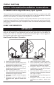
INSTALLING THE INDOOR UNIT
The indoor section should be installed before
proceeding with routing of refrigerant piping.
Consult the Installation Instructions of the indoor
unit (i.e.: air handler, furnace, etc.) for details
regarding installation.
CONNECTING REFRIGERANT
TUBING BETWEEN THE INDOOR
AND OUTDOOR UNIT
CAUTION:
This system utilizes R-410A refrigerant
with POE oil. When servicing, cover or
seal openings to minimize the exposure
of the refrigerant system to air to
prevent accumulation of moisture and
other contaminants.
General — Once outdoor and indoor unit
placement has been determined, route refrigerant
tubing between the equipment in accordance with
sound installation practices. Refrigerant tubing
should be routed in a manner that minimizes the
length of tubing and the number of bends in the
tubing. Refrigerant tubing should be supported
in a manner that the tubing will not vibrate or
abrade during system operation. Tubing should
be kept clean of foreign debris during installation
and installation of a liquid line filter drier is
recommended if cleanliness or adequacy of
system evacuation is unknown or compromised.
Every effort should be made by the installer
to ensure that the field installed, refrigerant
containing components of the system have been
installed in accordance with these instructions
and sound installation practices so as to insure
reliable system operation and longevity.
The maximum recommended interconnecting
refrigerant line length is 75 feet, and the
vertical elevation difference between the indoor
and outdoor sections should not exceed 20
feet. Consult long line application guide for
installations in excess of these limits.
Filter Dryer Installation — A filter dryer is
provided with the unit and must be installed in the
liquid line of the system. If the installation replaces
a system with a filter dryer already present in the
liquid line, the filter dryer must be replaced with
the one supplied with the unit. The filter dryer
must be installed in strict accordance with the
manufacturer’s installation instructions.
Optional Equipment — Optional equipment
(e.g.: liquid line solenoid valves, etc.) should
be installed in strict accordance with the
manufacturer’s installation instructions.
ELECTRICAL CONNECTIONS
WARNING:
Turn off all electrical power at the main
circuit box before wiring electrical
power to the outdoor unit. Failure to
comply may cause severe personnel
injury or death.
Wiring Diagram/Schematic — A wiring diagram/
schematic is located on the inside cover of
the electrical box of the outdoor unit. The
installer should become familiar with the wiring
diagram/schematic before making any electrical
connections to the outdoor unit.
Outdoor Unit Connections — The outdoor
unit requires both power and control circuit
electrical connections. Refer to the unit wiring
diagram/schematic for identification and location
of outdoor unit field wiring interfaces.
Control Circuit Wiring — The outdoor unit is
designed to operate from a 24 VAC Class II control
circuit. Control circuit wiring must comply with
the current provisions of the “National Electrical
Code” (ANSI/NFPA 70) and with applicable local
codes having jurisdiction.
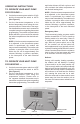
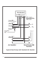
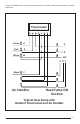
Thermostat connections should be made in
accordance with the instructions supplied with
the thermostat, and with the instructions supplied
with the indoor equipment. A typical residential
installation with a heat pump thermostat and air
handler are shown below.
Electrical Power Wiring — Electrical power
wiring must comply with the current provisions
of the “National Electrical Code” (ANSI/
NFPA 70) and with applicable local codes
having jurisdiction. Use of rain tight conduit is
recommended. Electrical conductors shall have
minimum circuit ampacity in compliance with the
outdoor unit rating label. The facility shall employ
electrical circuit protection at a current rating no
greater than that indicated on the outdoor unit
rating label. Refer to the unit wiring diagram for
connection details.