5 V1.00 2015.3.16 User Manual Thanks for your purchase of Tarot professional aerial photography products . To ensure your success with this product, we would like to introduce the following information and important notes ,hope it can be useful for you .
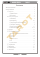
5 ASSEMBLY SECTION Contents Warning and Disclaimer . . . . . . . . . . . . . . . . . . . . . . . . . . . . . . . . . . . . 2 Product Introduction . . . . . . . . . . . . . . . . . . . . . . . . . . . . . . . . . . . . . . . 3 A. Product List . . . . . . . . . . . . . . . . . . . . . . . . . . . . . . . . . . . . . . . . . 4 1. Package Contents ... .... . ...... . ... . . ..... . . ... . .. 4 2. Self-prepared ......................................4 B. Mounting and Conguration . . . . . . . . . . . . . . .
5 ASSEMBLY SECTION Warning and Disclaimer Please DO NOT adjust the gimbal or change its mechanical structure! Before leaving the factory, ZYX-5D gimbal has been adjusted to t the camera and lens. Based on the setup procedures, you can achieve a fabulous ight experience. Please do not adjust the gimbal or change its mechanical structure. Moreover, do not add any component, such as a lter or lens hood, to the camera.
5 ASSEMBLY SECTION Product Introduction ZYX-5D, a great gimbal for model aircraft enthusiasts, can be widely applied to various model aircraft activities and entertainments. With unique internal wiring design, built-in IMU gimbal control module, specialized servo drive module, this gimbal is able to support three working modes, including Attitude Lock(AL) mode, Pan Follow (PF) mode and First Person View (FPV) mode.
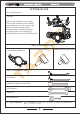
ASSEMBLY SECTION A.Product List 1. Package Contents Gimbal*1 With unique internal wiring design, built-in IMU gimbal control module, specialized servo drive module, this gimbal is able to support three working modes, including Attitude Lock (AL) mode, Pan Follow (PF) mode and First Person View(FPV) mode. Main Components Pack Lens RetainingPlate*1 Lens RetainingScrew* Camera Mounting Screws* Video Transmission Cable*1 AV Cable*1 Gimbal to Flight Control Cable USB Cable*1 Cable *5 USB module *1 2.
5 ASSEMBLY SECTION B.Mounting and Conguration 1. Camera Setup ①Set your camera to Tv (Shutter-Priority AE) or M (Manual Exposure). ②Turn (Live View shooting/Movie shooting Switch)to ③Press the button “AF.DRIVE”,set the drive mode to remotecontrol)or (Live View). (2-sec-self.timer/ (10-sec-self.timer/remote control). TIPs: ①In Manual Exposure, please set the ISO to Auto. ②Please adjust the shutter speed between 1/100 and 1/30 seconds.
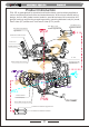
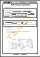
5 ASSEMBLY SECTION (2)Camera Mounting Camera Mounting Screw Lens Retaining Plate Screw ①Mount the camera into the gimbal. ②Tighten up the camera mounting screw. ③Tighten up the lens retaining plate screw. Attention: Please screw down both screws, otherwise vibrations might occur.
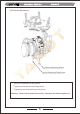
5 ASSEMBLY SECTION (3)Gimbal Mounting 165 mm (155 mm) 240 mm 96° 180° Mount the gimbal onto the landing gear. With some thread locker, tighten the mount screws. TIPs: ①Please DO NOT remove any screw in the gimbal during mounting. ②We have correctly adjusted the center of gravity of the gimbal. Please DO NOT change it based on your preference. ③The controller module with pin-port side should face to the head of the multi-rotor.
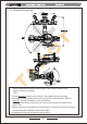
5 ASSEMBLY SECTION 3.Camera Connection and Camera Control Camera Connection ZYX-5D gimbal is able to transfer the transmitter signal to infrared signal. Please ensure the connection and setup between camera and gimbal are correct. Connect the gimbal video transmission cable to the A/V OUT/DIGITAL port of the camera. Attentions: Ensure that you have set the drive mode to (2-sec-self.timer/remote control) or (10-sec-self.timer/remote control).
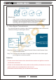
5 ASSEMBLY SECTION Attentions: If you want to control the camera through a 2-position switch. Please set your transmitter and observe the cursor of PVC channel in the assistant software. Either taking-photos or recording can be applied in this circumstance. 4. Video Signal Transmission You should prepare a wireless video transmission module and connect the cables according to the diagram below. Step One: Solder Power/Video Signal/Ground Cable to the Wireless Video Transmission Module.
5 ASSEMBLY SECTION 5.
5 ASSEMBLY SECTION TIPs: Battery Receiver Video Power Supply:3S-6S Li (11V-26V) * If you choose a battery to power up the gimbal and multi-rotor, please make sure this battery meets requirements of both components. 1. Common Receiver: connect the corresponding port of common receiver to CHI-CH7 channels of gimbal controller. Set related parameters in RECEIVER TYPE and RC MAPPING in assistant software. 2. FutabaSBUS Receiver/ SBUS-2 Receiver: connect SBUS receiver to CH7 channel of gimbal controller.
5 ASSEMBLY SECTION TIPs: When the MODE port is unconnected, the gimbal can only work in the DEFAULT mode. Moreover, during ight, if the MODE is unconnected suddenly, the working mode would remain the same before disconnection. After powering up the gimbal, if the receiver is unconnected, it works on DEFAULT MODE. Descriptions: Working Mode Mode Attitude Lock (AL)Mode Descriptions The angles of Roll, Pitch and Pan keep unchanged.
5 ASSEMBLY SECTION C.Flight Test Steps: 1.Please ensure all the wirings are correct and the power supply is in great condition. 2. Turn on the transmitter. 3. Powering up the gimbal and keep it still. After self-check,gimbal angle corresponds to INIT ANGLE in the assistant software. 4. Switch from different working modes to check the rotation direction in ROLL, PITCH, and PAN axis. TIPs: Before ight test, please ensure: 1.Correctly mount the camera into the gimbaland the gimbal onto the landing gear. 2.
5 ASSEMBLY SECTION D.ZYX-5D Assistant Software 1. Drive & PC Assistant Software Installation and Setup ①Please download the assistant software ZYX5D from http://www.0577mx.com/ ②Run the drive program in USB Driver folder and nish the installation procedures step by step. Please DO NOT ignore this step! Windows x86: “CP210xVCPInstaller_x86.exe”; Windows x64: “CP210xVCPInstaller_x64.exe”; ③Connect the USB module to the computer, and nish the installation. ④Run the assistant software ZYX5D.
5 ASSEMBLY SECTION 3. Basic Setup Methods to Connect the Receiver: Common Receiver: respectively connect to CH1-CH7 channel through 3P cables. SBUS Receiver: Connect to CH7 channel through a 3P cable. Satellite Receiver: connect to the satellite receiver DSM port. 1.Receiver Unconnected: set gimbal mode in Default Mode of assistant software. 2. Receiver Connected: set gimbal mode in MODE channel of the receiver.
5 ASSEMBLY SECTION 4. Channel Descriptions (1)Roll Channel Observe the rotation of the roll axis. Push the stick, and observe the rotation direction of the gimbal and the moving direction of the cursor. (2)Tilt Channel Observe the rotation of the tilt axis. Push the stick, and observe the rotation direction of the gimbal and the moving direction of the cursor. (3)Pan Channel Observe the rotation of the pan axis.
5 ASSEMBLY SECTION 5. Tools 1. Power up the gimbal and correctly connect to the assistant software. 2. Choose a correct receiver type and click “Write Parameters to Flash”. 3. Click “DSM RC Binding” button, and the gimbal will stop. 4. Connect Satellite Receiver to the corresponding port. Receiver LEDs will ash. 5. Turn on the Tx to bind. 6. After binding, power cycle the gimbal. Sensors Calibration When sensors suffer from squeezing, striking or violent changes of temperature, deviation might occur.
5 ASSEMBLY SECTION E.Troubleshooting Drifts occur in pan axis of AL Mode. 1. Sensor error is too large. 1. Calibrate sensors. 2.Flight control module is 2. Connect to ight control module. unconnected. Angle is not level. Gimbal vibrates. 1. Error of sensors is too large. 1. Calibrate sensors. 2. Tx is not centered. 2. Center the Tx. 1. The camera is not screwed down. 2. Motor torque is too large. 1. Screw down the camera and 18 lens screws. 2. Decrease motor torque value slightly.
5 ASSEMBLY SECTION F.Specications Input Power 3S-6S Li (11V-26V) 120mA(@25V) Working Current 180mA(@12V) 4000mA(@25V) Stall Current 8000mA(@12V) Working Environment Weight Dimensions -20℃~+50℃ 1510g 215x235x231mm TILT:±200 deg/sec Max Controllable Rotation Speed ROLL: ±200 deg/sec PAN: ±200 deg/sec TILT: -120°~+15° Controllable Rotation Range ROLL: ±25° PAN: ±360° continuous rotation Attitude Control Accuracy Supported Camera Supported Lens Assistant Software Supporting Platform ±0.
5 ASSEMBLY SECTION G.
5 ASSEMBLY SECTION H.LED Indicator Gimbal Controller RED, YELLOW and BLUE lights ash twice. Self-check process status RED, YELLOW and BLUE lights are constantly on. Self-check process fails. BLUE light ashes slowly. Work properly BLUE light ashes quickly. Bind with Satellite Receiver BLUE light turns off. Gimbal stops or stall pauses YELLOW light is constant on. Connection to Flight Control Module is normal. YELLOW light ashes.