» DA-78HR D00524000A Digital Multitrack Recorder OWNER’S MANUAL Ü ÿ Ÿ CAUTION: TO REDUCE THE RISK OF ELECTRIC SHOCK, DO NOT REMOVE COVER (OR BACK). NO USER-SERVICEABLE PARTS INSIDE. REFER SERVICING TO QUALIFIED SERVICE PERSONNEL. The lightning flash with arrowhead symbol, within an equilateral triangle, is intended to alert the user to the presence of uninsulated “dangerous voltage” within the product’s enclosure that may be of sufficient magnitude to constitute a risk of electric shock to persons..
Important Safety Precautions IMPORTANT (for U.K. Customers) For U.S.A TO THE USER DO NOT cut off the mains plug from this equipment. If the plug fitted is not suitable for the power points in your home or the cable is too short to reach a power point, then obtain an appropriate safety approved extension lead or consult your dealer. If nonetheless the mains plug is cut off, remove the fuse and dispose of the plug immediately, to avoid a possible shock hazard by inadvertent connection to the mains supply.
IMPORTANT SAFETY INSTRUCTIONS CAUTION: … Read all of these Instructions. … Save these Instructions for later use. … Follow all Warnings and Instructions marked on the audio equipment. 1) Read Instructions — All the safety and operating instructions should be read before the product is operated. 2) Retain Instructions — The safety and operating instructions should be retained for future reference. 3) Heed Warnings — All warnings on the product and in the operating instructions should be adhered to.
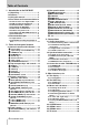
Table of Contents 1 - Introduction to the DA-78HR 1.1 Unpacking ......................................... 7 1.2 Features............................................. 7 1.3 Using this manual............................. 7 1.4 Precautions and recommendations 8 1.4.1 Clock source in a digital studio....... 8 1.4.2 HR recording and emphasis ............ 8 1.4.3 Environmental conditions ................ 8 1.4.4 Installing the DA-78HR ..................... 9 1.4.5 Electrical considerations ................. 9 1.
Table of Contents 4.8 TC chase menu..................................25 4.9 TC generator menu ...........................25 4.10 MIDI menu ........................................25 4.11 Maintenance menu..........................26 4.12 Dedicated keys ................................26 5 - Basic operations 7.1.1 Setting MEMO 1 and MEMO 2 “on the fly” ......................................................38 7.1.2 Checking, editing and manually entering MEMO 1 and MEMO 2...............38 7.1.
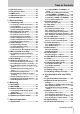
Table of Contents 8.5.1 Recording while formatting.............. 51 8.6 Individual clock mode ...................... 51 8.7 Error messages.................................51 9 - Operations related to timecode 9.1 ABS and timecode ............................ 52 9.1.1 ABS time ............................................ 52 9.1.2 Tape timecode................................... 52 9.1.3 Selecting TC or ABS timing ............. 52 9.2 Tape timecode mode ........................ 52 9.2.1 TAPE TC setting ...
1 - Introduction to the DA-78HR The TASCAM DA-78HR is a digital audio multitrack recorder designed for use in a variety of applications, including video post-production and audio multitrack work. It records 8 tracks of full-quality digital audio on standard Hi8 video cassettes using a speciallydesigned transport and head mechanism.
1 - Introduction to the DA-78HR We suggest that you make a special note of the section 1.4, “Precautions and recommendations” as these contain some information which is unique to the DA-78HR. 1.4.1 Clock source in a digital studio We also suggest that you also read , as this will help you when you come to perform basic operations.
1 - Introduction to the DA-78HR water. Do not use abrasive cleaners or solvents such as alcohol or thinner. Avoid subjecting the DA-78HR to jolts, sudden shocks, etc. NOTE — I MP OR TANT If you have to return the unit for service or repair, use the original packing materials if possible. If the unit is to be transported to a recording location, etc., use a suitable transport case with sufficient shock protection. TASCAM does not accept responsibility for damage resulting from neglect or accident. 1.4.
1 - Introduction to the DA-78HR There are two basic types of Hi8 tape: MP and ME. Each has its own particular characteristics and merits: • MP tapes are manufactured using a daubed magnetic particle deposit process and exhibit a level of performance which is more than acceptable. They have a durability which allows them to be used as work tapes in studio and post-production environments. • ME tapes have their magnetic layer produced through a metal evaporation process.
1 - Introduction to the DA-78HR 1.5.2 Available recording and playback time Depending on whether the tape has been purchased for use with an NTSC (P6/E6) or a PAL/SECAM (P5/E5) television system, the same length of tape (as far as video length is concerned) will provide different times for audio work, as shown below, due to different frame rates between television systems.
2 - Front and rear panel features 12 TASCAM DA-78HR
2 - Front and rear panel features Legend 2.1 General controls and indicators Meaning Section Machine or timecode offset is in 8.3.1 and operation 9.6.2 When both of these are lit, the DA-78HR is using internal word CLOCK (WORD)sync, and when neither is lit, word sync is being received through the REMOTE IN/ 3.2 SYNC IN connector. If one is lit, the word sync is being CLOCK received through the appropri(DIGITAL IN) ate connector (digital audio (COAXIAL) or word sync).
2 - Front and rear panel features transport momentarily goes into stop mode before the tape starts fast-winding. B STOP key Cancels any current tape transport mode, and stops the tape. If pressed in chase mode, cancels the mode and stops the tape. C PLAY key Starts playing the tape. If this key pressed while recording is in progress, the DA-78HR drops out of record mode. D RECORD key If the PLAY key C is pressed while the RECORD F SHIFT key and indicator Controls the behavior of the other keys (see 4.
2 - Front and rear panel features M REPEAT (MENU) key and indicator This key is used to provide a repeat function between the two location points (see 7.2, “Repeat function”). When the DA-78HR is shift mode, it allows selection of the top-level menus (see 4.3, “Menus and submenus”). N CHASE (SUB MENU) key and indicator This key is used to set the DA-78HR to a slave chase mode, either to another DTRS unit, or to timecode (see 8.2.3, “Master/slave settings (CHASE mode)” and 9.6, “Chasing to timecode”).
2 - Front and rear panel features X REMOTE PUNCH IN/OUT Use this to connect an optional RC-30P footswitch to control punch operations. Y TDIF-1 (DIGITAL I/O) c ANALOG INPUTS (unbalanced) This connector carries the digital signals to and from the DA-78HR in TEAC Digital Interface Format (TDIF-1). This connector carries 8 balanced inputs at a nominal +4 dBu level. This allows convenient and reliable single-cable connection to the GROUP outputs of a suitably-equipped console such as the TASCAM M1600 series.
3 - Connections This section explains how to connect other equipment to the DA-78HR. It is not intended as a complete reference to the use of the DA-78HR. See the appropriate sections for full details of how these connectors are used.
3 - Connections 3.1.4 SPDIF connectors 3.2.3 Timecode connections The coaxial RCA digital audio connectors on the rear panel allow connection of an SPDIF-equipped device (e.g. a DAT recorder). The DA-78HR can be synchronized to externallygenerated timecode and is also equipped with an internal timecode generator.
3 - Connections apart from the audio connections (either digital or analog). If more than one DTRS unit is to be used, the first unit in the chain must have its Machine ID set to “1”, (“0” in the case of DA-88s) and subsequent units must have their IDs set in order with no gaps in the numbering sequence. Note that the diagram below does not show any audio connections. Machine ID 1 (master) Machine ID 2 (slave 1) 3.3.
4 - Menu interface, etc. Read this section to understand the basic principles of the menu operations. These menus are used for making settings which cannot be made directly from dedicated front panel keys. In addition, this section gives a brief description of the top-level menu groups as well as the sub-menu items and the parameters. This is not a detailed description of these menus and parameters, but may be consulted for quick reference.
4 - Menu interface, etc. 4.3 Menus and sub-menus When the unit is in shift mode, the REPEAT ( MENU) key is the “gateway” to the menus. This key is used to show the top level groups of the menu tree: 4.3.1 Exiting menu mode To exit menu mode, either: • turn off the shift mode (press the SHIFT key so that its indicator is no longer flashing) or SYSTEM-- SYSTEM-- Basic system parameters and functions • enter another shifted function (except for the shifted MENU or SUB MENU functions) AUDIO.
4 - Menu interface, etc. 4.3.5 “Left” and “right” keys When editing time values, etc. it is useful to be able to edit one particular element (i.e. hours, minutes, seconds or frames) of the time value. When displayed as a sample value, the number of samples per frame varies, according to both the sampling rate, and the frame rate currently selected: Sampling frequency → The “cursor” is indicated by a flashing dot following the “field” currently being edited.
4 - Menu interface, etc. the current position of the knob and the current parameter value do not match. 3 When the SHUTTLE/DATA indicator knob blinks rapidly, the current position of the knob matches the current parameter value. Turning the knob from this position will now allow the parameter value to be changed. 4 Turn off the “data entry” mode using the SHIFT and SHUTTLE/DATA key combination. Until the match described above has been made, the value of the parameter cannot be changed using the knob.
4 - Menu interface, etc. Values (*=default) Display REC. MUTE. (rec mute) ALL OFF. *, ALL ON or individual Described in 7.10, “REC MUTE (recording silence)” 4.7 TC menu TC -- The following parameters are used to control timecode operations: tracks ON or OFF TAPE. TC 4.6 AUDIO2 menu (tape TC) Audio. 2. -- This menu provides additional audio parameter settings: Values (*=default) Display C. FADE.
4 - Menu interface, etc. 4.8 TC chase menu Display TC. CHS -- The following parameters are used to control the DA-78HR operations when chasing to an incoming timecode signal: (TC recording enable) Described in STRT. Time (TC generator) INDiv. REC (individual recording) 0* (off), 1 (on) 9.6.11, “Individual recording while chasing timecode” (rechase mode) RECHASE * (rechase), FREE (free) 9.6.9, “Rechasing timecode” (rechase window) (TC generator mode) 1 SEC*, 2 SEC (1 or 2 seconds) 9.6.
4 - Menu interface, etc. 4.11Maintenance menu 4.12Dedicated keys MAINTN-- The following (shifted) keys also allow settings to be made. These are fully described in the appropriate sections of the manual: The following menu provides information relating to maintenance procedures, etc. Display version (version) Values (*=default) SYS (system).* Frnt (front), Svo Described in 11.3, “Checking version numbers” (servo) Key (drum time) TOTL* (total), SRCH (search) 11.1.
5 - Basic operations This section explains some of the basic operations using the DA-78HR. Section 7, “Advanced operations” describes more advanced operations. Most operations on a DA-78HR are similar to those on a traditional analog multitrack recorder, but we suggest that you read this section and the next to learn about the features of the DA-78HR. 5.1 Formatting a tape Before you use a tape in the DA-78HR, you must first format it.
5 - Basic operations recorder. Of course, a non-HR (16-bit) recording made on the DA-78HR can be replayed on any DTRS recorder. 7 To start formatting the tape, hold down the RECORD key and press the PLAY key. NOTE The tape counter may show a negative ABS time for a short while at the start of the formatting process. While it is displaying a negative value, no audio recording can take place. 8 The tape will format to the end, and then rewind automatically. You are now able to use the tape for recording.
5 - Basic operations Hi8 cassette write tabs work in the opposite manner to DAT cassettes, and “closed” means “writeprotect”. If the tape is write-protected, eject the tape, open the write-protect tab, replace the cassette, and try again. • Sony Hi8 cassettes (and those from some other manufacturers) have the words “SAVE” (write-protected) and “REC” (write-enabled) molded into the cassette shell by the protection tab. 5.2.4 Recording the first tracks (i) 1 Arm the tracks on which you wish to record.
5 - Basic operations signals or to perform track-bounce operations with the SPDIF ( COAXIAL) input selected. Note that whatever digital source is selected, the appropriate clock must be selected. If you are recording from (say) a CD player, which typically cannot accept a word clock, as well as from a TDIF-1 source (e.g. a TASCAM digital mixer) the DA-78HR must be set to accept the clock from the DIGITAL IN (see 5.2.2, “Selecting a clock source”).
5 - Basic operations 2 Enter shift mode, and enter the sub-mixer mode. 5.4.1 Sampling frequency and word length 3 Make the level and pan settings for the tracks which are to be combined, as described in 7.4, “Sub-mixer”. See this section for full details of how to operate the sub-mixer.
5 - Basic operations If you are unsure about the difference between monitoring modes as implemented on the DA-78HR, now is a good time to read 6, “Monitoring”. Obviously you will want to record while you listen to the off-tape signals from previously-recorded tracks and the input source on tracks where recording is taking place. 5.6 Punch-in and punch-out There are a number of ways in which the DA-78HR can be used to perform reliable punch-in and punchouts automatically.
5 - Basic operations NOTE If you do not want to change to source monitoring on the punch track(s) between the punch points when setting the points, do not set the REC FUNCTION on for these tracks. At any time when the RHSL indicator is lit or flashing, this means that recording will not actually be carried out, even if the RECORD key and/or the REC FUNCTION indicators are lit. 7 At the point where you want to punch out, press PLAY. The REC FUNCTION indicator of any armed tracks will start flashing again.
5 - Basic operations 5 Press the CLEAR (PRE ROLL ) key once more so that the display shows PO 0003 (PO 0003), i.e. the post-roll time. Since there is little point in setting pre- and post-roll times to frame accuracy, you can only set these values to second accuracy. The minimum values you can set are 5 seconds (preroll) and 3 seconds (post-roll) and the maximum value is 59 minutes 59 seconds for both. 1 While the tape is running, press the LOC 1 key (there is no need to press STOP first).
5 - Basic operations 3 If you want to record the punch-in again, press the AUTO IN/OUT key so that the indicator flashes, and repeat the process described above. 4 If you are satisfied with the punch-in, follow the steps below, otherwise, press LOC 1 to return to the punch-in point, press the AUTO IN/OUT key so that the indicator flashes, and repeat the take. 5.6.9 Exiting punch-in mode 1 Disarm any armed tracks (press the REC FUNCTION switches so that the indicators go out). 2 Press the CLEAR key.
6 - Monitoring NOTE NOTE We strongly advise you to read this section – the effective use of multitrack monitoring is one of the keys to an efficient recording session. ALL INPUT overrides any shuttle monitoring selections described below. Any shuttle monitoring while ALL INPUT is on will always be source monitoring. Like all multitrack recorders, the DA-78HR has a number of different monitoring modes, depending on the current monitor status, transport status and whether the track is armed or not.
6 - Monitoring 6.5 Summary of monitor modes The following table shows what will be monitored from a track. This depends on the ALL INPUT, AUTO REC FUNCTION PLAY MON and the REC FUNCTION settings, and on the transport mode currently engaged.
7 - Advanced operations 7.1 Autolocation The DA-78HR contains two location memories, accessible through the LOC 1 and LOC 2 keys. These also allow a “A↔ B repeat” facility, which allows you to rehearse part of a mixdown, for instance. These two location memory points are referred to as “MEMO 1” and “MEMO 2”. As with the punch recording points (5.6, “Punch-in and punch-out”), it is possible to set and edit these points in a number of ways. 7.1.
7 - Advanced operations If you press PLAY twice while the tape is locating, the PLAY key will light steadily, the tape will stop and playback will start immediately. If you have only set one location point, the repeat will be between “00:00:00.00” and the location point. If you are using the DA-78HR with a remote control unit, and you have have pressed the AUTO PLAY key on the remote control unit, replay will start automatically when the location point is reached.
7 - Advanced operations 7 Press and hold the SHIFT key for more than three seconds to exit the delay setting mode. The meters can also be used to give a visual indication of the track delay. Press SHIFT and one of the REC FUNCTION keys (as described in 4.1.1, “Peak positive values meters”) to toggle this meter mode off and on. The default 0 (zero) at power-on is for this mode to negative values be on. The track delay, expressed in seconds, is between –4 to +150 milliseconds.
7 - Advanced operations The display will show the level and pan position of the channel. For example, L. 02. P -Cwould indicate a level of 102 and a center pan position. 3 Use the ▲ and ▼ keys and/or the knob to change the level of the active channel. 4 To change the level of another channel, press that channel’s REC FUNCTION key. The meters may be used to show the value of the channel levels (the default is for this function to be on, and it may be toggled with the SHIFT+ REC FUNCTION combination).
7 - Advanced operations 2 Use the ▲ and ▼ keys to change the value (maximum +6.0%, minimum –6.0%, in 0.1% steps). Reset the value to 0.00% by pressing and holding either of the ▲ or ▼ keys, and pressing the other. 3 Press the SHIFT key to turn off the setting mode. The VARI SPEED indicator will continue to be lit, showing that varispeed is currently enabled. 4 Turn off varispeed (when the VARI SPEED indicator is lit) by pressing the VARI SPEED key to turn the indicator off.
7 - Advanced operations 2 Press the SUB MENU key until the display shows RLs. (RLS —release) and then changes to the current value for that setting. 7.10REC MUTE (recording silence) 3 Use the ▲ and ▼ keys to change the value between the FAST ( FAST), SLOW ( SLOW) and MED ( MEDIUM) settings. There may be times when you wish to prevent any signal from reaching an armed track (in other words, when you record, you are recording silence onto the track. 7.
7 - Advanced operations (for instance 16, the DA-78HR’s non-HR tape word length) to improve quantization. 1 Press the SHIFT key so that the unit is in shift mode ( SHIFT indicator is flashing). Paradoxically, this technique of adding noise removes quantization noise and distortion at low signal levels and improves the overall distortion figures.1 2 Press the MENU key until the display shows Audio. 2-- ( AUDIO2--).
7 - Advanced operations Pressing the ▲ and ▼ keys simultaneously returns the output patchbay to the normal state. Track 8 Track 7 Track 6 Track 5 Track 4 Track 3 Track 2 Track 1 The meters display the current assignments of tracks to the output channels. In this case, each meter shows the assignment status of the correspondingly-numbered output channel (not track), as shown here. Press SHIFT and one of the REC FUNCTION keys (as described in 4.1.1, “Peak meters”) to toggle this meter mode off and on.
7 - Advanced operations 2 Press the SHIFT key so that the SHIFT indicator is flashing, and press the MENU key until the display shows system-- ( SYSTEM--). 3 Press the SUB MENU key until the display shows Load. OFF ( LOAD OFF ). 4 Press the ▲ key to make the DA-78HR ready for loading the settings. The display will show READY ( READY). 5 Press the ▲ key again to actually start the restore operation.
8 - Synchronization with other DTRS units This section describes the techniques and methods to be followed when the DA-78HR is linked to other DTRS units (e.g. TASCAM DA-98, DA-38, DA-88 and of course other DA-78HR units). 8.2 Machine ID and master/slave settings Up to 16 DTRS units can be linked, for a total of 128 digital tracks. Each DTRS unit in the chain must be assigned a machine ID. The unit at the head of the chain (the master) should have ID number 1.
8 - Synchronization with other DTRS units standard sequence, working from the head of the chain to the end. NOTE 8.2.2 Setting machine ID When chasing, it may take some time before chase lock is achieved. A slave unit cannot start recording until it has achieved chase lock status. 1 Press the SHIFT key so that the SHIFT indicator is flashing, and press the MENU key, until the counter shows SYSTEM-(SYSTEM--). 8.3 Machine offset 2 Press the SUB MENU key until the display shows id. sel.
8 - Synchronization with other DTRS units 2 Press and hold down the ▲ key and press the ▼ key to reset the value. Machine offset will now be cancelled and the at the correct time relative to the dialog and reference tracks. Copy of video worktape audio tracks OFFSET indicator will go out. 8.3.3 Setting machine offset “on the fly” As well as entering an absolute number, it is also possible to enter a number “on the fly” as the tapes are playing.
8 - Synchronization with other DTRS units 5 Select “all digital” as the input source on the target slave (5.3, “Input selection”). 8.4 Digital dubbing S O UR CE M AS TE R 6 Put the target slave machine into CHASE mode (8.2, “Machine ID and master/slave settings”). 7 Locate the master tape to a point before the material you want to duplicate. P W - 88 S (s y n c c a b le ) P W - 88D o r P W - 88 DL ( d ig it a l I/O c a bl e ) The target slave will also locate since it is in chase mode.
8 - Synchronization with other DTRS units 3 Press the CHASE key on all of the slave DTRS units. The indicator will flash. 4 Press FORMAT/Fs twice within five seconds, on each of the DTRS units (master and all slaves) so all machines are ready to start formatting. If you press the CLEAR key while the FORMAT indicator is lit steadily, you will cancel the format operation. 5 Select the same sampling rate (48 kHz or 44.1 kHz) on each DTRS unit.
9 - Operations related to timecode The DA-78HR contains synchronization facilities, including a SMPTE/EBU timecode generator, which allow it to act either as a timecode master or a timecode slave when connected in a timecode chain. If timecode is recorded on tape, a special discrete subcode track is used, which leaves all eight tracks free for recording and playback of audio material. Note that this subcode is available both as analog SMPTE/EBU timecode and also as MTC.
9 - Operations related to timecode 2 Press the SUB MENU key until the display briefly shows TAPE. TC ( TAPE TC), followed by the current setting. 3 Use the ▲ and ▼ keys to change the value of this parameter between TC TRK ( TC TRK) and CONV ABS ( CONV ABS ). TC TRK means that timecode recorded on the tape will be used as the source for the timecode. CONV ABS means that the ABS time (subcode) will be converted to timecode and output as timecode. 9.2.
9 - Operations related to timecode 9.4.1 Showing input timecode There are two primary reasons for the DA-78HR to receive timecode: when the DA-78HR is chasing to timecode, and must receive the master timecode, and when the DA-78HR is to record timecode from another unit (but see 9.5.5, “External timecode sources” below). To view incoming timecode, follow the procedure below: 1 Press the SHIFT key so that the SHIFT indicator is flashing, then press the MENU key until the display shows TC-- ( TC-- ).
9 - Operations related to timecode To set the MTC output on or off: 9.4.6 Timecode output timing 2 Press the SUB MENU key until the display shows MTC ON ( MTC ON ) or MTC OFF (MTC OFF). Because of the nature of the digital-to-analog conversion, the timecode which is output from the DA78HR must be synchronized to match the audio timing from either the digital or the analog audio outputs, whichever set of outputs is in use at the time.
9 - Operations related to timecode If you are recording timecode only, we suggest that you do not use external sources for recording timecode. Set the source to TAPE TC as described immediately above, and use ABS (see 9.2.2, “ABS setting”) as the tape timecode source. This will ensure an accurate match between the timecode and the ABS timing reference (the fact that the generator must be started manually means that there will not be a tight relation between timecode and the ABS timing).
9 - Operations related to timecode 9.5.5 External timecode sources The following notes should help you when you must record timecode on the DA-78HR from an external source (analog or digital). As mentioned earlier, you should only need to record timecode from an external source when the audio and timecode tracks have to be transferred together, keeping a strict relationship between the audio and timecode tracks.
9 - Operations related to timecode 9.5.8 Checking the frame mode of striped timecode locked to the incoming timecode, the CHASE indicator will light steadily. To view the frame mode of a tape which has been striped with timecode, follow the steps below: S 1 Press the SHIFT key so that the SHIFT indicator is flashing, then press the MENU key until the display shows TC-- ( TC-- ).
9 - Operations related to timecode 4 Use the ▲ and ▼ keys to set the offset for the slave DA-78HR, and the SHIFTed ▲ and ▼ keys to move the cursor to the different fields. You can also use the OFFSET key as a right cursor key. These functions allow you to measure and test the optimum pre-roll position for the DA-78HR (when it is a timecode slave) to park itself relative to the master timecode device so that it will lock up and start playing quickly.
9 - Operations related to timecode absolute difference. The “relative difference” is expressed as below: Relative difference = Absolute difference – Offset Thus, if the offset is set on a slave machine to +00:10:00.00 (10 minutes) and while chasing, the two machines’ counters read as follows: Master Slave 10:15:12:12 10:05:12:08 the slave is now 10 minutes and 4 frames behind the master. timecode master tape includes a break in the timecode, though, you may want the DA-78HR to rechase the master.
9 - Operations related to timecode 2 Press the SUB MENU key so that the display shows INDV. REC ; ( INDV REC x) where x is 0 (disabled) or 1 (enabled). 3 Use the ▲ and ▼ keys to choose between 0 (disabled) and 1 (enabled). 61 TASCAM DA-78HR When this function is enabled, individual recording is possible when chasing to timecode, and when it is disabled, all slave units follow the master’s lead.
10 - MIDI control 10.1MMC enable and disable The DA-78HR can be controlled using MIDI Machine Control Commands (MMC). To enable and disable the DA-78HR’s response to these commands: 1 Press the SHIFT key so that the SHIFT indicator is flashing, and then press the MENU key until the display shows MIDI-- ( MIDI--). 2 Press the SUB MENU key until the display shows MIDI on or MIDI OFF ( MIDI ON or MIDI OFF). 3 Use the ▲ and ▼ keys to make the appropriate setting.
10 - MIDI control 10.2MMC Bit Map Array Commands unavailable on the DA-78HR are struck through, as for example (RECORD PAUSE).
10 - MIDI control Byte r0 r1 r2 r3 r4 Bit 7 Bit 6 (40H) Bit 5 (20H) Bit 4 (10H) Bit 3 (08H) Bit 2 (04H) Bit 1 (02H) Bit 0 (01H) 0 (06) GENERATOR TIME CODE (05) LOCK DEVIATION (04) ACTUAL OFFSET (03) REQUESTED OFFSET (01) SELECTED TIME CODE (00) reserved 0 (0D) GP5 (0C) GP4 (0B) GP3 (0A) GP2 (02) SELECTED MASTER CODE (09) GP1 0 0 0 0 (14) (13) (12) (11) (10) (1B) (1A) (19) (18) (17) (08) GP0/LOCATE POINT (0F) GP7 (16) (07) MTC INPUT (0E) GP6 (15) 0 (26) Short GENERATOR TIM
10 - MIDI control 10.4.2 TASCAM Exclusive messages 10.3MIDI Control Change It is also possible to send use MIDI Control Change messages to control the sub-mixer parameters, as described here: Parameter MIDI Control Hex value Channel fader Volume (7) 0x07 Channel pan Master fader Pan (10) Control (9) 0x0a 0x09 Channel mutea Control (11) 0x0b a. Values of 0 through 63 turn mute on, values of 64 through 128 turn it on.
10 - MIDI control 10.4.6 Track Copy Setup = 09 is either the input channel number – 1 (00 through 07) or the tape track number – 1 + 8 (08 through 0F). There are two data bytes: and . 10.4.7 Track Copy Enable is the tape track number – 1 (00 through 07) =0a 1 byte of data to enable or disable the function. 0 = disable, 1 = enable.
10 - MIDI control 10.5MIDI Implementation Chart TA S CA M M ul ti t ra ck Di gi t al R e co rd e r d a te :1 99 9 .0 9. 2 0 Mo d el D A -7 8H R M I DI I m pl em e nt at i on C h ar t V er si o n : 1 .
11 - Maintenance, etc. 11.1Head and transport cleaning The DA-78HR incorporates an internal cleaning mechanism that not only cleans the rotary head, but also the tape as it enters the tape path. The provision of this cleaning mechanism significantly reduces the need for manual cleaning. If, despite the internal cleaning mechanism, the PB CONDITION indicator 6 lights, the heads are dirty and manual cleaning procedures should be followed.
11 - Maintenance, etc. 4 Play the suspect tape. The track meters are used to show the error rate at different location, as listed below: Tape edge (head A) Tape edge (head B) Tape center (head A) Tape center (head B) display shows MAINTN-- ( MAINTN-- — maintenance). 2 Press the SUB MENU key until the display briefly shows DRUM. TIM ( DRUM TIM—drum time) . The display then changes. 3 Use the ▲ and ▼ keys to choose between d. ;;;; ( D xxxx —total drum time) and d. s. ;;;; ( D.S.xxxx—drum search time).
11 - Maintenance, etc. the front panel software) or SVO. ;. ;; ( SVO x.yy—the servo software). The x.yy here represents the software revision number (e.g. 1.00). 3 Use the ▲ and ▼ keys to display the required software component version number. 11.3.1 Software upgrades TASCAM pursues a policy of continuous improvement to products, and there may be future enhancements to the DA-78HR software. Your TASCAM dealer will be able to advise you of developments in this area.
12 - Options, specifications and reference 12.1Options for the DA-78HR You can purchase a number of options through your TASCAM dealer. 12.1.1 RC-898 remote control unit This full-function remote control unit can control up to six DTRS units, in addition to VTRs and analog audio devices. With 99 location point memories, and an easily-visible display and dedicated keys, this unit represents one of the most sophisticated options available for controlling a DTRS system. 12.1.
12 - Options, specifications and reference 12.2Specifications 12.2.1 Tape recorder section Format Recording method DTRS/DTRS-HR format Rotary-head, helical-scan method Tape type Head construction Hi8 MP tape / Hi8 ME 2 x record, 2 x playback Tracking method Erasure method ATF (Automatic Track Finding) Overwrite Drum speed Tape speed 2,000 r.p.m. 15.955 mm/sec. Equivalent tape speed Maximum recording time 4.2 m/sec. 108 min.
12 - Options, specifications and reference 12.2.9 Physical specifications 482mm (19. 0 in. ) 57m m (2. 25 i n.) 132m m (5. 2 in. ) 330m m (13 in. ) 10mm (0.4 in.) 143m m (5.6 in.) 9.5m m (0. 4 in.) 456mm (18. 0 in. ) 432mm (17. 0 in. ) Size (including feet) w x hx d 482 x 143 x 350 (mm) 19 x 5. 6 x 13.8 (in) Weight 8.1 kg (17.8 lbs) 12.2.10Power specifications Power requirements Power consumption Applicable Electromagnetic Environment Peak inrush current USA/Canada 120 VAC, 60 Hz U.K.
Index A - F A aborting the format process 28 ABS and timecode 52 ABS frame rate 52 ABS setting 53 ABS time 52 absolute and relative difference 60 absolute difference 60 absolute time see “ABS time” adjusting parameter values 21 advanced output options 44 ALL ANALOG setting 31 ALL INPUT 14, 36 ambient temperature 8 analog inputs 72 analog inputs (balanced) 16 analog inputs (unbalanced) 16 analog outputs 72 synchronizing with timecode 55 analog outputs (balanced) 16 analog outputs (unbalanced) 16 audio connec
Index G - O frame mode 53 striped timecode 58 frame rate 53 ABS timing 52 G generating timecode 56 generator modes 56 grounding 9 H head cleaning 68 head time 69 HR mode 7–8 emphasis 8 I ID see "machine ID" IF-88SD SDIF-2 digital audio converter 71 IF-AE8 AES/EBU digital audio converter 71 IF-TAD ADAT digital audio converter 71 “indirect” word sync 19 individual clock mode 51 individual recording while chasing timecode 60 input patchbay routing 30 input selection 29 input timecode display 54 input word l
Index P - S oscillator 43 output advanced options 44 patchbay 44 word length 44 overdubbing 31 P parameter values, adjusting 21 park position 59 peak hold time 42 peak meters 15, 20 Physical specifications 73 physical specifications 73 pitch control see “varispeed” playback (repeat) 39 playback times 11 post-roll time see also “pre-roll time” 33 ~ IN (POWER IN) 16 power cord 7 power specifications 73 power supply 9 powering the unit off and on 9 pre-roll and post-roll (punch) 33 pre-roll time editing 33 lo
Index T - W SPDIF connectors 18 input/output 16 Specifications 72 STOP key 14 sub-frame values 22 sub-menus 21 sub-mixer 40 input sources 41 master level 40 setting levels and pan positions 40 summary of monitor modes 37 synchronization connections 18, 47 formatting 50 PW-88S cable 47 with other DA units 47 with other DTRS units 47 synthesizing timecode from ABS timing 56 SYSTEM menu 23 T tape brands 10 tape errors 68 tape head cleaning 68 tape length 11 Tape recorder section 72 tape timecode 52 tape types
» DA-78HR TEAC CORPORATION Phone: (0422) 52-5082 3-7-3, Nakacho, Musashino-shi, Tokyo 180-8550, Japan TEAC AMERICA, INC. Phone: (323) 726-0303 7733 Telegraph Road, Montebello, California 90640 TEAC CANADA LTD. Phone: 905-890-8008 Facsimile: 905-890-9888 5939 Wallace Street, Mississauga, Ontario L4Z 1Z8, Canada TEAC MEXICO, S.A. De C.V Phone: 5-658-1943 Privada De Corina, No.