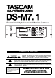
D00671100A Professional Digital Surround Monitor Controller OWNER’S MANUAL Ü ÿ Ÿ CAUTION: TO REDUCE THE RISK OF ELECTRIC SHOCK, DO NOT REMOVE COVER (OR BACK). NO USER-SERVICEABLE PARTS INSIDE. REFER SERVICING TO QUALIFIED SERVICE PERSONNEL.
Important Safety Precautions IMPORTANT (for U.K. Customers) For U.S.A TO THE USER DO NOT cut off the mains plug from this equipment. If the plug fitted is not suitable for the power points in your home or the cable is too short to reach a power point, then obtain an appropriate safety approved extension lead or consult your dealer. If nonetheless the mains plug is cut off, remove the fuse and dispose of the plug immediately, to avoid a possible shock hazard by inadvertent connection to the mains supply.
IMPORTANT SAFETY INSTRUCTIONS CAUTION: … Read all of these Instructions. … Save these Instructions for later use. … Follow all Warnings and Instructions marked on the audio equipment. 1) Read Instructions — All the safety and operating instructions should be read before the product is operated. 2) Retain Instructions — The safety and operating instructions should be retained for future reference. 3) Heed Warnings — All warnings on the product and in the operating instructions should be adhered to.
Table of Contents 1 – About the unit Installing the DS-M7.1.................................6 2 – Parts of the DS-M7.1 Front panel...................................................8 Function keys.................................................. 9 Rear panel ....................................................11 3 – Connections Connecting the console ..............................13 Connecting the tracking recorder ..............13 Connecting the mastering (stem) recorder14 A note on the word clock ....
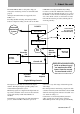
1 – About the unit The TASCAM DS-M7.1 is designed to help you manage the monitoring of mixes of surround sound projects. CAM DM-24 and digital multitrack (tracking) recorders as well as the multitrack recorder being used to master the surround mix (the stem recorder), the DS-M7.1 can be used for monitoring of the mix as it comes off the console, as well as the recorded mix from the mastering recorder, with the push of one front panel key. All major surround formats are supported, from LCRS to 7.1.
1 – About the unit allowing almost every common industry format to be supported by the DS-M7.1. Full calibration facilities are provided, with a built-in pink noise generator, to allow for quick, easy and accurate setup of the unit. Channel delay is provided to compensate for acoustic delay when surround speakers are used in a large space. An analog or digital insert can be placed in the monitoring path, in order to hear the surround mix through a surround encoder.
1 – About the unit Using the front panel as a remote control unit When you use the front panel as a remote con- nector, where the cable may be routed more conveniently. trol unit, you have the choice of using either the front or rear 9-pin D-sub connector. If the DS-M7.
2 – Parts of the DS-M7.1 Front panel The part of the front panel of the unit which houses the display and controls can be removed and connected via an appropriate cable, up to 20m (60ft.) in length by turning the captive thumbscrews at the top of the panel counterclockwise.
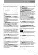
2 – Parts of the DS-M7.1 Function keys These keys all have two functions: the unshifted function, as shown by the label above the keys, and the color-coded (to match the SHIFT key) shifted function, as shown by the lower label. The shifted function is enabled when the SHIFT indicator is lit. 4 STATUS/INPUT The STATUS key brings up the Status screen, where the settings relating to the master status of the system can be viewed (but not changed). As the INPUT key, it is used to route and assign the inputs.
2 – Parts of the DS-M7.1 I TEST Used in setup to turn the internal pink noise generator on and off. See the Setup Guide for details. K BASS MGT Turns the bass management function on and off (settings are made with the BASS MGT function key) J DOWN MIX/MONO Switches between the L MUTE ALL Cuts all the monitor signals selected surround format and the currently-selected downmix mode (the downmix mode is selected using the SYSTEM function key). simultaneously.
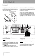
2 – Parts of the DS-M7.1 Rear panel See the section on Connections for details of how to make connections to and from the DS-M7.1. 1 2 3 4 7 8 with three expansion slots, which can take different types of I/O card. Consult your TASCAM dealer for details concerning the availability and the fitting of these cards. When a card is fitted, it can be used as an alternative to one of the three connectors immediately to the right of the slots, as described below.
2 – Parts of the DS-M7.1 8 MASTER RECORDER I/O There are three sets of connectors for connecting the master recorder: TDIF-1 (combined input and output), ADAT (separate input and output “lightpipe” connectors) and AES/EBU (combined input and output). 9 REMOTE IN 1 Use this as an alternative to the front panel REMOTE IN 2 connector when using the front panel as a remote control. See “Making up a remote control cable” on page 38 for details. A RS-232C Reserved for future software upgrades.
3 – Connections This section describes not only the connections you make between other equipment and the DS-M7.1, but also the software steps necessary to make that other equipment recognizable by and usable with the unit. Read this section carefully, especially the section on word clock, as it is essential to the proper operation of your system, and may even result in damage to your equipment if the appropriate steps are not carried out. NOTE When making connections between the DS-M7.
3 – Connections the console outputs, and may not be monitored directly from the DS-M7.1. 1 Outputs to the tracking recorder These connect to the recorder inputs. These may be monitored as BUS signals from the DS-M7.1. When this connection, together with all other connections, have been made, you should set up the DSM7.1 to recognize the appropriate tracking recorder source (TDIF or slot), as described here.
3 – Connections Console and MasterRec (mastering recorder). The second and third lines of the screen will be automatically filled in depending on both the source and the settings made elsewhere in the system as described in “Routing and patching” on page 19. Possible values are: Source Possible sources High-speed connections cannot be made using the TASCAM DM-24 digital mixing console.
3 – Connections Error Meaning number Appropriate action to take 7 Frequency error The master clock is not a recognized frequency (e.g. 32 kHz). Check the master settings and correct, if necessary. 8 AES/EBU preamble error (normal) At normal sampling frequencies, the preamble of the AES/EBU signal acting as the clock source cannot be read by the DS-M7.1. Check and correct settings on the clock master. 9 AES/EBU preamble error (high-speed) At high sampling frequencies (88.
3 – Connections 1 Press the SYSTEM key, and use the cursor keys until a screen similar to the following appears: [SYSTEM] MonOut 2 < Use the VALUE control to select between POST (the digital signals mirror the analog signals) and PRE (the parameters described above are ignored). POST Other monitoring settings There are other system settings related to the monitor system, which affect the analog outputs and the digital outputs in “post” mode.
3 – Connections Dimmer and mute control connections A remote box for mute (MUTE ALL) and dimmer control may be made up and used so that the control of these functions can be carried out from a location in the listening environment other than the main mixing location. than the open/closed status of the switch triggers the change in the unit’s status. Use non-latching push-to-make switches wired to a common sleeve ground with the dimmer wired to ring, and the mute to the tip of a standard 3.5mm stereo plug.
4 – Routing and patching When the physical external connections have been made, it is time to set up the internal connections within the DS-M7.1 as described here. Since project needs and applications vary, the DSM7.1 provides flexibility in the way in which incoming signals are received and monitored. Choosing the surround format First, you must decide in what format the incoming signals are to be processed. The available options are: 7.1, 6.1, 5.1, LCRS (LS, RS), LCRS (CS) and LR.
4 – Routing and patching 1 With the SHIFT indicator lit, press the STATUS/INPUT key so that the screen displays the following: [INPUT SUM ROUTER] Format LCRS(LS,RS) Input Output 12345678 1 *------- 2 Use the cursor keys to navigate to the set the value (VALUE control) to one of those listed above. Input parameter, and As you select the surround pattern, note how the green indicators under each MUTE CONTROL key light and go out, reflecting the surround pattern you have selected.
5 – Using the DS-M7.1 Once you have set up the connections, assigned the inputs and outputs, and followed the procedures in the Setup Guide, you can start using your DS-M7.1. Dimming the output Press the DIM key to dim the output by the amount set in “SPL Reference Level” on page 17. The DIM key lights when active.
5 – Using the DS-M7.1 The parameter to the left on the second line allows you to choose between the two types: TYPE1 and TYPE2. 80/100/120 Hz 48dB/oct Type 1 L HPF L C HPF C R HPF R LS HPF LS HPF RS RS -15 / 0 dB (-15dB default) LFE SW LPF -5/ +10 dB (-5dB default) LC LC RC RC Type 2 80/100/120 Hz 48dB/oct -12.0 dB L L -1.5 dB C C HPF -12.0 dB R R -1.5 dB LS RS HPF LS HPF RS -15 dB SUB LFE LPF -5 dB SW LPF (default OFF) LC LC RC RC 22 TASCAM DS-M7.
5 – Using the DS-M7.1 Type 1 bass management When type 1 bass management is selected, the screen looks something like this: [BASSMGT] SUB ON LFE>LFE The amount of LFE signal added to the TYPE1 MCH>LFE-15.0 FRQ 120 LFE>LFE This is set together with the LFE>LFE parameter as described below. -5.0 FRQ The frequency at which the crossover occurs: LFE monitor channel. This is set together with the MCH>LFE parameter described above.
6 – Note on DS-M7.1 usage Many pre-mixes for film are made that are greater than 8 tracks. The DS-M7.1 can still be useful in these conditions, as explained here. If a large format (24 or more output busses) console is used, a number (8 or 16) of the busses can be used to feed the stem recorder. Stem recorder tracks return via faders The returns from the stem recorder can then be fed back through the console inputs and routed to a different set of eight busses, which are then used to feed the DS-M7.
7 – Downmixing Downmixing, as explained earlier, is the process of folding a surround mix into a format using fewer channels. This is done for the purpose of checking compatibility. Downmixing is enabled and disabled on the DSM7.1 using the DOWN MIX/MONO key under the SPL readout and control. When downmixing is active, the key is lit (it flashes in mono downmix mode, see below). Available downmix targets Source pattern 6.1 5.1 LR MONO 5.1 LCRS 4.
7 – Downmixing 7.1 formats L L L L R R R R C C C mute C mute LFE mute LS mute RS mute LC mute RC -3/-4.5/-6dB -4.5/-6/-7.5/ -9dB LFE LFE LFE -3/-6/-9/ dB LS LS LS -0/-3/-6/ RS RS RS -3dB LC mute LC LC mute RC RC -1.5/-3/-4.5/-6dB RC -1.5/-3/-4.5/ -6dB 7.1 > 5.1 7.1 > LR L L -3dB R C R mute C mute LFE mute LS mute RS mute LC mute RC -3/-4.5/-6dB LFE -3/-6/-9/ dB LS -0/-3/-6/ RS -3dB LC -1.5/-3/-4.5/ -6dB RC 7.1 > mono 26 TASCAM DS-M7.
7 – Downmixing 7.1 > 5.1 In the 7.1 to 5.1 downmix, the attenuation 7.1 > mono In the 7.1 to mono downmix, the values are: attenuation values are: Source > Target Values in dB (default underscored) Source > Target Values in dB (default underscored) LC>L, RC>R -1.5, –3, –4.5, –6 C > L+R –3, –4.5, –6 LC+RC > C –4.5, –6, –7.5, –9 LFE>L+R –3, –6, –9, –∞ LS,RS>L+R 0, –3, –6, –∞ LC,RC>L+R –1.5, –3, –4.5, –6 7.1 > LR In the 7.
7 – Downmixing 6.1 format L L L L R R R R C C C mute C mute LFE mute LS mute RS mute LC mute RC -3/-4.5/-6dB LFE LFE LFE -3/-6/-9/ dB LS LS LS RS RS RS LC CS (LC) -0/-3/-6/ CS (LC) mute -3/-4.5/-6dB RC RC mute B -3/-6/-9/ RC 6.1 > 5.1 6.1 > LR L L -3dB R R C mute C mute LFE mute LS mute RS mute LC mute RC -3/-4.5/-6dB LFE -3/-6/-9/ dB LS -0/-3/-6/ RS CS (LC) -3/-6/-9/ RC 6.1 > mono 28 TASCAM DS-M7.
7 – Downmixing 6.1 > 5.1 In the 5.1 to 5.1 downmix, the attenuation 6.1 > mono In the 6.1 to mono downmix, the values are: attenuation values are: Source > Target Values in dB (default underscored) Source > Target Values in dB (default underscored) CS (LC)>LS,RS -3, –4.5, –6 C > L+R –3, –4.5, –6 LFE>L+R –3, –6, –9, –∞ LS,RS>L+R 0, –3, –6, –∞ CS(LC)>L+R –3, –6, –9, –∞ 6.1 > LR In the 6.
7 – Downmixing 5.1 format L L L L R R R R C C C mute C -3/-4.5/-6dB dB -3/-6/-9/ -3/-6/-9/ LFE dB mute LS LFE LFE LFE LS LS LS RS RS RS -3dB RS LC mute LC LC mute LC RC mute RC RC mute RC 5.1 > LCRS 5.1 > 4.1 L L L R R R C C C mute -3/-4.5/-6dB -3dB R mute C mute LFE mute LS -3/-4.
7 – Downmixing 5.1 > LCRS In the 5.1 to LCRS downmix, the attenuation values are: 5.1 > LR In the 5.1 to LR (stereo) downmix, the attenuation values are: Source > Target Values in dB (default underscored) Source > Target Values in dB (default underscored) LFE >C –3, –6, –9, –∞ C >L,R –3, –4.5, –6 LFE>L,R –3, –6, –9, –∞ LFE>L,R –3, –6, –9, –∞ LS,RS>L,R 0, –3, –6, –∞ 5.1 > 4.1 In the 5.1 to 4.1 downmix, the attenuation values are: 5.1 > mono In the 5.
7 – Downmixing LCRS format L L L R R R C C C mute -3dB R mute C mute LFE mute LS -3/-4.5/-6dB -3/-4.5/-6dB LFE S (LS) L mute LFE LFE mute LS S (LS) -0/-3/-6/ -0/-3/-6/ RS mute RS RS mute RS LC mute LC LC mute LC RC mute RC RC mute RC LCRS > LR As mentioned earlier, there are two LCRS configurations. The first is the LCRS (LS, RS) configuration, This allows a control room set up for 5.1 or 6.1 to use an LCRS configuraiton without repatching the speakers.
7 – Downmixing LR format L L -3dB R C R mute C LFE mute LFE LS mute LS RS mute RS LC mute LC RC mute RC LR to mono LR > mono In the LR to mono downmix, there are no parameters (changeable attenuation values) TASCAM DS-M7.
8 – Specifications The following information is provided for reference when connecting the DS-M7.1 to other equipment. Always take care when making these connections. 13 This shows the pinouts when viewing the rear panel of the DS-M7.1. 1 25 14 Analog connections The pinouts for the 25-pin D-sub connectors used for both analog input and analog output are as follows: Pin Signal Pin Signal Pin Signal Pin Signal 13 NC 14 CH. 8 – 15 CH. 7 + 16 CH. 7 Gnd 1 CH 8 + 2 CH. 8 Gnd 17 CH.
8 – Specifications Specifications I/O specifications CONSOLE I.
8 – Specifications Audio performance Analog outputs Master recorder input(AES/EBU) -> Monitor output(Analog) T.H.D < 0.004% 1kHz 0dBFSinput, Fs=48kHz S/N > 113dB Fs=48kHz, A-weight Dynamic range > 113dB 1kHz -60dBFS input, Fs=48kHz, A-weight Frequency response < ±0.5dB 20Hz-20kHz, 1kHz 0dBFS input, Fs=48kHz < +0.5/-1.5dB 20Hz-40kHz, 1kHz 0dBFS input, Fs=96kHz > 100dB 100dB1kHz 0dBFS input, Fs=48kHz Crosstalk Master recorder input(AES/EBU) -> Analog insert output(SLOT3 : IF-AN/DM) T.H.
8 – Specifications General specifications Sampling frequencies supported: Word length Voltage requirements Power consumption Applicable electromagnetic environment Peak inrush current Dimensions (main unit) w x h x d Dimensions (main unit with remote control and cable) wxhxd Dimensions (remote control unit, excluding cable) wxhxd Weight (main unit) Weight (remote control unit) Operating temperature Supplied accessories 44.1kHz, 48kHz, 88.
8 – Specifications Making up a remote control cable It is possible to make two kinds of remote control cable, allowing the front panel of the DS-M7.1 to be detached and used as a remote control unit. The second type (extended) allows remote control up to 20 m (over 65 feet) away, and must be constructed using a specially-specified cable (described here). The first type may be up to 5 m (about 15 feet) long (standard cable), and may use a general-purpose cable.
8 – Specifications Block diagram Analog insert I/O SLOT3 in ADC TDIF ADAT AES example : IF-AN/ DM DAC RCV out in DRV RCV out in DRV RCV out RCV in DRV DRV out example : IF-AE/DM MASTER SEL RTN BUS RTN/BUS TRKREC SEL SLOT2 TDIF 1 2 3 4 5 6 7 8 ANA DIG CONSOLE SEL 1 2 3 4 5 6 7 8 Input summing router DISABLE ENABLE INSERT ENABLE/DISABLE INSERT DIGITAL/ANALOG INSERT PRE SUM/POST SUM SLOT1 TDIF Output router SRND SRND ST L SRND ST SRND ST SRND ST SRND ST ST SR
» DS-M7.1 TEAC CORPORATION Phone: (0422) 52-5082 3-7-3, Nakacho, Musashino-shi, Tokyo 180-8550, Japan TEAC AMERICA, INC. Phone: (323) 726-0303 7733 Telegraph Road, Montebello, California 90640 TEAC CANADA LTD. Phone: 905-890-8008 Facsimile: 905-890-9888 5939 Wallace Street, Mississauga, Ontario L4Z 1Z8, Canada TEAC MEXICO, S.A. De C.V Phone: 5-851-5500 Campesinos No.