
User Manual


8
TASCAM ML-32D / ML-16D
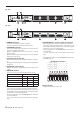
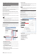
Rear panel
ML−32D
ML−16D
7 PRIMARY connector
This is the main Dante transmission connector.
Use this to connect to a Dante network all the time.
8 SECONDARY connector
This is the secondary Dante transmission connector. The use
changes depending on the mode.
When in redundant mode, this connects to the secondary
Dante network.
When in switched (daisy chain) mode, use to connect another
Dante device in the chain.
9 Link status/activity indicator
Green indicates that a link is established between the devic-
es.
Blinking indicates that signals are being transmitted between
the devices.
0 Gigabit link status indicator
Orange indicates that a gigabit Ethernet link has been estab-
lished.
q REF. LEVEL switches
Use these to set the analog input/output reference level.
Max level/Reference level Switch
+24 dBu/+4 dBu
3 3 3
+22 dBu/+4 dBu
3 3 c
+20 dBu/+4 dBu
3 c 3
+18 dBu/+4 dBu
3 c c
+15 dBu/+6 dBu
c 3 3
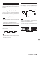
w ANALOGOUTPUT 1-8/9-16/17-24/25-32 connectors
These are 25-pin D-Sub balanced analog output connectors.
Use analog output D-Sub multi-cables to connect these to
external balanced analog input devices and transmit signals
for channels 1–8, 9–16, 17-24 and 25-32.
The pin assignments* of the ANALOG OUTPUTS connectors
are as shown below.
(1-8, 9-16, 17-24 and 25-32 connectors follow the same pat-
tern.)
e ANALOG INPUTS 1-8/9-16/17-24/25-32 connectors
These analog input connectors are balanced D-Sub 25-pin.
Use analog input D-Sub multi-cables to connect these to ex-
ternal balanced analog output devices and transmit signals
for channels 1–8, 9–16, 17-24 and 25-32.
The pin assignments* of the ANALOG INPUTS connectors are
as shown below.
(1-8, 9-16, 17-24 and 25-32 connectors follow the same pat-
tern.)
*
Pin assignments adhere to the TASCAM DB-25 Pinout Stan-
dard (AES59-2012)
1
14
25
13
ch 25
ch 26
ch 27
ch 28
ch 29
ch 30
ch 31
ch 32
24 23 22 21 20 19 18 17 16 15
12 11 10 98765432
17-24 INPUTS / OUTPUTS
25-32 INPUTS / OUTPUTS
ch 17 ch 18 ch 19 ch 20 ch 21 ch 22 ch 23 ch 24
ch 9
ch 10
ch 11
ch 12
ch 13
ch 14
ch 15
ch 16
1-8 INPUTS / OUTPUTS
9-16 INPUTS / OUTPUTS
ch 1 ch 2 ch 3 ch 4 ch 5 ch 6 ch 7 ch 8
ANALOG INPUTS / OUTPUTS
r AC IN connector
Plug the included power cord in here.