» MMP-16 Modular Multitrack Player OWNER’S MANUAL D00000000A
CAUTION RISK OF ELECTRIC SHOCK DO NOT OPEN CAUTION: TO REDUCE THE RISK OF ELECTRIC SHOCK, DO NOT REMOVE COVER (OR BACK). NO USERSERVICEABLE PARTS INSIDE. REFER SERVICING TO QUALIFIED SERVICE PERSONNEL. The lightning flash with arrowhead symbol, within an equilateral triangle, is intended to alert the user to the presence of uninsulated “dangerous voltage” within the product’s enclosure that may be of sufficient magnitude to constitute a risk of electric shock to persons.
IMPORTANT SAFETY INSTRUCTIONS CONSIGNES DE SECURITE SICHERHEITSHINWEISE NORME DI SICUREZZA INSTRUCCIONES DE SEGURIDAD VEILIGHEIDSVOORSCHRIFTEN TEAC CORPORATION
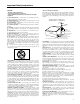
Important Safety Instructions CAUTION: • Read all of these Instructions. • Save these Instructions for later use. • Follow all Warnings and Instructions marked on the audio equipment. 1) Read Instructions — All the safety and operating instructions should be read before the product is operated. 2) Retain Instructions — The safety and operating instructions should be retained for future reference. 3) Heed Warnings — All warnings on the product and in the operating instructions should be adhered to.
Tascam MMP-16 Owner’s Manual Chapter 1 General Information ...................................................................... 9 MMP-16 Introduction ....................................................................................................................... 9 Hardware Overview ........................................................................................................................ 10 Functional Overview...........................................................................
Front Panel Indicators, Switches, and Displays.............................................................................. 37 LED Indicators ............................................................................................................................................ 37 Configuration Settings ............................................................................................................................. 37 Active Mode/Key Indicators ..............................................
Serial Transport ....................................................................................................................................... 76 Editor ...................................................................................................................................................... 76 Varispeed ................................................................................................................................................ 76 User Settings........................
WORD CLOCK IN Connector................................................................................................................... 105 WORD CLOCK OUT Connector ............................................................................................................... 105 VIDEO IN/OUT Connector........................................................................................................................ 105 VITC IN Connector ...............................................................
Chapter 1 General Information This chapter presents the main features and capabilities of the MMP-16 hardware and a functional overview of its Panel/Display states. MMP-16 product specifications are also included.
The MMP-16 will directly play back material created on Digidesign Pro Tools or WaveFrame digital audio workstations, as well as OMF Compositions which reference Sound Designer II audio media files. The disk drive or drives containing edited Session, Project, or OMF files are simply “unplugged” from the workstation and then “hot-plugged” into the MMP-16, using the standard internal Kingston hard drive carrier, or otherwise connected to the MMP-16’s external SCSI port.
A 40-character (two line by 20-character) LCD (Liquid Crystal Display) serves as the MMP-16 status and control text window. The top line typically shows the machine status and current time code or feet/frames location, while the bottom line shows various time code registers (memory, slip. etc.) and accepts input from the front panel. The entire display may also alert the operator to any machine or user error conditions.
Functional Overview The MMP-16 operates in any of eight different Panel/Display states (simply referred to as “states” for convenience). These states are distinguished by the nature of the information displayed in the LCD window and by which keys are functionally available while in that state. These MMP-16 Panel/Display states are described here. Normal state is the default Panel/Display state on power-up.
The MMP Backup state is accessed via the Load Track state by pressing SHIFT+SLIP after choosing (scrolling to) the desired Project while in the LOAD TRACK state. This state is similar to the Setup state in that it has menu choices which are accessed by using the Up/Down arrow keys or the Wheel. The key choices available in the Backup state are the same as those in the Setup state, hence it exists at the same level of the hierarchy of panel/display states as the Setup state.
EErrrroorr V Veerriiffyy LLooaadd,, V Viieew w,, SSlliipp TTrraacckk SSeettuupp,, B Baacckkuupp N Noorrm maall Figure 1-3. MMP-16 Panel/Display State Hierarchy STATE NORMAL SETUP LOAD TRACK VIEW TRACK SLIP TRACK VERIFY ERROR BACKUP LCD WINDOW DISPLAY Shows current play head time on top and selected time register on bottom of display. COMMENT Default at startup. Allows direct access to SETUP and TRACK states, all keys functional.
System Specifications Analog Output Level:+4 dBu balanced, +24 dBu clip, nominal levels trim pot adjustable Headroom:20 dB above nominal level Analog Output Impedance:10k, balanced / <75 ohms, balanced Output Adjustment Range:+10 dBu - +25 dBu, clipping / +18 dBu - +25 dBu, clipping THD+N:<.004 % @ 1 kHz, @ clip level -0.
Electrical Ratings: 115 VAC @ 2A, 50-60Hz 230 W Max -OR230 VAC @ 1A, 50-60Hz 230 W Max Nominal temperature should be 41 to 95 degrees Fahrenheit (5 to 35 degrees Centigrade). Relative humidity should be 30 to 90% (non-condensing) Analog input/output is 12.28 VRMS Max Weight is approximately 37 Pounds ( 16.78 Kilograms) with a hard disk loaded.
Chapter 2 Installation This chapter covers the physical installation of the Tascam MMP-16 as either a stand-alone recording/playback system or as part of a larger, multiple unit digital dubber system. Descriptions are given of the various connectors on the MMP back panel. Both general installation procedures and specific application installations are covered.
General Guidelines Mounting Rack Ears The MMP-16 is a self-contained sixteen channel digital playback device designed to be mounted in a standard 19” (48.26 cm) IEC equipment rack in either the mix studio or a dedicated machine room in a professional audio recording facility. As such, each MMP-16 is housed in a steel chassis 19-inches (48.26 cm) wide by 17 ¼ inches (43.81 cm) deep by 7-inches (17.78 cm) tall. Each MMR-8 requires 5U (7inches or 17.78 cm) of rack space.
Installing Multiple MMP Units Multiple units can be mounted one on top of the other when forced air rack ventilation is provided. A oneinch clearance is required on both sides of the MMP-16. In facilities with raised computer room-style flooring, a ventilation opening in the floor is recommended. In no case should the internal rack temperature ever exceed 110 degrees Fahrenheit (43 degrees Centigrade) during normal operation (as measured at the rear of any of the MMP-16s in the system).
AC Mains and Grounding (Earthing) Considerations Each MMP-16 requires one AC mains connection. A standard six-foot (1.83 Meter) power cordset is included with each MMP-16 wired for the USA standard. A six-foot (1.83 Meter) AC Mains cordset for use in Europe, proper for the country of use will be supplied by your TASCAM dealer. The AC mains outlet must be capable of delivering 230 watts (2 amps) for each MMP-16 in the system. The main power supply has a 115/230 VAC switch on the back of the unit.
MODEL NO. 115 / 230 ~, SERIAL NO. 2.0 / 1.0 A, PARALLEL TRACKS MMP-16 PARALLEL TRANSPORT THIS DEVICE COMPLIES WITH PART 15 OF THE FCC RULES. OPERATION IS SUBJECT TO THE FOLLOWING RESTRICTIONS: (1) THIS DEVICE MAY NOT CAUSE HARMFUL INTERFERENCE, AND R MODULAR MULTITRACK PLAYER TEAC CORPORATION (2) THIS DEVICE MUST ACCEPT ANY INTERFERENCE RECEIVED, INCLUDING INTERFERENCE THAT 50 - 60Hz MADE IN USA LISTED XXDK UL1950 E1XXXX MAY CAUSE UNDESIRED OPERATION.
Audio Connections All audio outputs (both analog and digital) of the MMP-16 use DB-25 connectors. The pin configuration used on the DB-25 analog audio connectors is identical to that used for Tascam DTRS format digital tape machines such as the DA-88. Two female DB-25 connectors are used for the analog connections, one for channel 1-8 and the other for channels 9-16, as labeled on the MMP back panel.
Timecode and Video Reference Signals To accurately synchronize the MMP-16 to film or video, or with other audio playback equipment, some method of providing a stable timing reference must be used. Because the MMP-16 is very flexible, there are numerous methods one could use to connect film and video equipment. The best method depends upon the chosen method of sync, the other equipment that is being controlled, and whether the MMP-16 will be the master or a slave to the other equipment.
Biphase Connections Biphase is a control signal typically generated by a film projector and is traditionally used to interlock the operation of the film with sprocketed magnetic tape machines. The Biphase Operations Board (BOB) on the back panel of the MMP has four biphase input connections and one biphase output connection for synchronizing the operation of the MMP-16 to film transports. Use Setup Menu 100, Sync Group, to select which of the four Biphase inputs (Sync Groups) will control the system.
The MMP MIDI OUT connector carries a MTC signal generated by the MMP-16 whenever the unit is in Play. To slave MIDI devices that can follow MTC (MIDI Time Code) to the MMP-16, connect the MMP MIDI OUT connector to MIDI In port of the external device. The MIDI out signal (and the MIDI Through signal, if it is set as a second MIDI output) will contain any MMP-16 responses to the MMC input commands in addition to MTC generated by the MMP-16 from the time code reference source.
Serial Transport Connection The TRANSPORT connection uses the industry-standard RS-422 Sony 9-pin P2 protocol (Ampex VPR-3 is also supported) for controlling external serial transports such as audio or videotape machines. It is intended for transport control of a single external device. This port will send out the appropriate transport commands when the transport functions of the MMP are engaged through the front panel or via the MMRC Remote controller.
Using the PC Keyboard Use the keyboard to perform the following data entry tasks on the MMR or MMP: • • • • • • Enter Project and Track names directly by using the standard alphanumeric keys. Enter Tape Mode Start time, Pre-Roll and Post-Roll directly using the number keys. Access Menu Banks directly by using the Number keys. Use the Up and Down arrow keys on the keyboard to scroll through the Setup Menus. Use the Up and Down arrow keys to scroll through menu parameters.
Connecting External SCSI Media The MMP-16 SCSI interface card is pre-set to SCSI ID 7. The internal removable drive in the MMP-16 is set to SCSI ID 0. Each device added in the SCSI chain must have a unique SCSI ID number or else the MMP-16 will not boot properly. External SCSI connections should be made using the shortest possible length of double-shielded SCSI-2 cables with 110 ohms impedance. Only the last drive in the chain is terminated.
Remote Controllers for the Tascam MMP-16 Tascam MM-RC The TASCAM MM-RC is a dedicated remote control unit designed specially for use with the MMP-16 and the MMP-16 sixteen channel player unit. It connects to a special remote connector on the UI/B card on the back of the MMR and MMP units. This remote allows complete control of all attached functions of the MMR and MMP units, including all setup menus. It also allows for machine grouping as well as system wide control of all attached units.
Powering Up the System The MMP-16 comes from the factory with the operating system and MMP-16 software pre-loaded onto the internal hard drive. At POWER ON, the front panel LCD should display the following message: Tascam MMP-16 © TimeLine 1996 - 97 If this message is not seen, the front panel is not operating correctly, and you should contact Tascam technical support for assistance.
4. Connect the MMP-16 to the applicable timing reference source and to the appropriate remote control interface a. To connect the MMP-16 to a film transport, connect the biphase sync output from the projector to one of the four biphase inputs. The four biphase inputs are numbered 1 - 4 from top to bottom. Any, or all, of the inputs can be connected. Use Setup Menu 100, Sync Group, to select which of the four Biphase inputs (Sync Groups) will control the system.
Factory Default Settings The MMP-16 is shipped from the factory using a pre-defined set of operating parameters. The factory default settings can be changed in the field at any time through a system of Setup menus that control the MMP-16 operating parameters. The new value settings will be automatically saved and used at system start-up as the normal operating parameters of the MMP-16.
Chapter 3 MMP-16 Operation MMP-16 Keys & Definitions Throughout this manual several abbreviations and written shortcuts are used to define user operations and machine functions. The following summarizes how these abbreviations and text shortcuts relate to the operational description: Keys Shift Key Refers to the colored front panel keys on the MMP-16. The gray keys are used to enter time code numbers (on the numeric keys) and to perform various other common functions. The shift key is the only yellow key.
34 Mode This term is used to refer to the active Control mode selected by Setup menu 000 and to refer to the Track Select Mode which governs the behavior of the SEL keys. It may also be used to refer to various operational modes such as Loop, Trim, or Shift which change the meaning of other keys or controls as long as the mode is active. LCD Text To indicate the front panel LCD text, curly brackets are used to enclose the text. (e.g., {X.
MMP-16 Front Panel Key Groups and Displays Assigned Machine Identification Configuration Status LEDs Track Status and Metering LEDs Liquid Crystal Display (LCD) TASCAM MMP-16 POWER REFERENCE 2 3 4 5 6 7 8 9 10 11 12 13 14 15 16 CLIP CLIP CLIP CLIP CLIP CLIP CLIP CLIP MAX MAX MAX MAX MAX MAX MAX MAX +12 +12 +12 +12 +12 +12 +12 +12 +6 +6 +6 +6 +6 +6 +6 +6 0 0 0 0 0 0 0 0 -6 -6 -6 -6 -6 -6 -6 -6 -12 -12 -12 -12 -12 -12 -12 -12 SAMPL
36
Front Panel Indicators, Switches, and Displays Collectively, all the front panel keys and the Wheel are called switches and the LEDs, six motion control lamps, and the Liquid Crystal Display (LCD) are called indicators. The MMP-16 is manually controlled through front-panel switches, while system status is shown via the indicators. The front panel switches are divided into five groups: the track group, the keypad group, the setup & wheel group, the wheel itself, and the transport (or motion control) group.
Meter LEDs Each track has its own column of signal level LEDs that read the MMP-16 analog output signal off disk. Each meter column contains eight LEDs. Functioning much like a tape machine’s peak meters, their meters have a fixed rise time of <30 ms and a default decay time of <0.5 seconds. The bottom level LED (-25) is a green presence indicator. Any time there is signal on the track there will be an indication. The next three LEDs indicate signal levels of -12, -6 and 0 VU.
Liquid Crystal Display (LCD) The LCD or “display” consists of two lines of twenty characters that show various operator messages (time code, user prompts, error messages and information, track data, and setup menu information) depending upon the active panel/display state. Both lines of the LCD can also show various system messages according to the operating state.
In the Normal state, the bottom line of the display shows time code (or feet & frames) that has been entered manually, captured, or recalled from one of the memory or special-purpose registers. There is a label in front of the time code (or feet & frames) to indicate what register is being displayed. The “Label” identifies the memory or register that is currently being displayed through these abbreviations: SYNC, OFST, RDR, TIME, FREE, HEAD, TAIL, IN, OUT, NEXT, PREV, and MEM n (where n = 0 - 9).
Slip Track State Display In the Slip Track state, the display will show the current time position in the top line of the display (the same as in the Normal state), while the bottom line of the display is used to show the contents of the slip register for the selected track. If more than one track is selected, all of their registers are active, but only the last selected track indexes slip register will be shown. 01234567890123456789 LCD character positions (left to right) Label HH:MM:SS:FF.
To move a loaded track from its current Track index position into the selected Track index or to load a currently unloaded track into the selected Track index, scroll through the list of available tracks until the desired track is located. The display will indicate your choice of both the selected track to be moved or loaded, and the destination Track index. Press the STO key to complete the operation and load the track.
Verify State Display In the Verify state, the display is used for operator interface messages which usually request a Yes/No answer or require a number to be entered (such as a password) before normal operation can be resumed.
Front Panel Key Groups The MMP-16 front panel keys and controls are divided into five functional groups, the Transport Group, the Setup & Wheel Group, the Wheel itself, the Track Group, and the Keypad Group. Transport Group These keys consist of the On Line, Rewind (<<), Reverse Play (<), Stop (o), Play (>), and Fast Forward (>>), keys. These transport functions are analogous to those found on tape dubbers.
Setup and Wheel Group This group of keys contains the SETUP and arrow keys, and the TRIM, JOG, and SHTL (shuttle) keys. These keys are located on the right section of the front panel, directly over the wheel and below the right end of the LED display panel. The Setup and Wheel Group keys are used to navigate through the various choices in the Setup menus and to control the operation of the Wheel. These keys also have shifted functions indicated in the text above the keys.
JOG Pressing JOG stops the transport and allows the Wheel to “scrub” over the current location at a speed relative to the motion of the wheel. The minimum Jog speed is Play/8 (3 octaves down), and maximum is 1.5 times nominal speed. Jog is typically used to play audio at slow speed to locate to a particular spot in pre-recorded material in order to identify an edit or punch point. Sound is produced in the Jog mode only as long as the wheel moves.
Track Group These keys are located at the left central portion of the front panel under the track meters. Although the SEL keys are active all the time, they affect tracks according to which Track Select Mode (EDIT, MON, LOAD TRACK, TRACK, SLIP) is active. The active mode is indicated by the amber LED above the keys, while the active track(s) for that mode are indicated by the amber LEDs above the SEL keys.
Cut Cut removes the audio from the selected track(s) between the In point and the Out point and places it into the clipboard, while pulling up (slipping earlier in time) all subsequent events by an amount equal to the length of the cut track segment. In Out Before Cut After Cut Audio after Out is shifted earlier in time To Clipboard Copy Copy places a copy of the material that is between the In and Out points on the selected track(s) into the clipboard without altering the audio events on the track(s).
Insert Insert places the contents of the clipboard into the selected track(s) at the In point time, while moving all subsequent events “down stream” (later in time) by the length of the inserted event(s). Clipboard contents In Before Insert Out After Insert Audio after Insert is shifted later in time Open Open places a segment of silence into the selected track(s) equal to the time between the In point register and the Out point register.
EDIT Pressing this key (while in the Normal state) allows the SEL keys to select which track(s) will be later edited (using the SHIFT+SEL edit functions described above). The suggested sequence of keystrokes to follow for editing is: Press the EDIT key to enter the Edit Track Mode, then the SEL key for the track(s) to be edited. Set the In and Out points to define the range of material to be affected on the selected track(s). Press SHIFT + SEL for the desired edit function (Cut, Clear, Copy).
Edit Sync Mode The setting chosen in Setup Menu 221 - Edit Sync Mode – determines which point in the audio material to be pasted or inserted from the clipboard will be used as the sync reference point for the edit. This is a very important consideration, since the end result of the edit operation may be very different depending on the current setting of this menu parameter when the edit is performed. The two parameters for this menu are Sync at In Point and Sync at Playhead.
SHIFT+EDIT (EVENT) Loads the start and end of the event currently under the play head on the selected track(s) into the In point and Out point registers (also called “event capture”). MON Pressing this key while in the Normal state allows the SEL keys to select which track(s) will be monitored through the front panel headphone monitor output. This does not affect the rear panel Studio Monitor jack, which always presents a mono mix of all tracks.
When LOAD TRACK is first pressed, the LCD will show a list of all WaveFrame Projects, Pro Tools Sessions, or OMF Compositions on all mounted volumes. The wheel or arrow keys are used to scroll through the various choices (if multiple choices are available) and to display the name of each of the available files. To view the next lower level of the EDL hierarchy (Episode, Reel, Act, Dub or Track), for the currently displayed Project, Session, or Composition, press LOAD TRACK again.
SHIFT+TRACK (UNLOAD) The shifted function of the TRACK key allows “unloading” of a loaded track, and will return the track to the “blank” state, as well as returning the loaded track back to the pool of unloaded tracks, which can then be viewed using LOAD TRACK. Note that tracks may be loaded or unloaded even while the MMP is playing. This is a very convenient feature of the MMP and allows for auditioning alternate tracks during playback or loading tracks from different projects.
Keypad Group These keys are located in the central portion of the front panel, directly under the LCD.
OFFSET (SHIFT+1) This display-only register represents the time difference between the MMP-16’s time code and the time code being chased. When locked to the Lynx bus, this equals the time difference between the MMP-16’s time code and the Lynx master time code. In either case, the offset is equal to the MMP-16 time minus the time code being chased. READER (SHIFT+2) This display-only register shows the current time code being chased by the MMP16.
HEAD (SHIFT+8) This read-only register shows the start time of the first edit on the currently loaded tracks. Tracks selected while in the EDIT track select mode govern the operation of this function. If no tracks are selected in the EDIT track select mode, the MMP will scan across all loaded tracks to find the first edit location.
SHIFT The yellow SHIFT key functions like a locking keyboard shift key. When active, it modifies those keys that have a shift function assigned to them (identified by the function name written above the gray keys). Pressing and releasing the yellow Shift key causes the shift LED to turn on, indicating SHIFT is active. Pressing a gray key with a shift function will then perform the shifted function and turn off the yellow Shift LED.
LOOP Pressing the Loop key prepares the MMP transport for performance of one of several possible types of loop sequences relative to the In and Out time code registers. To start looping after LOOP is pressed and the In and Out times are set, press the appropriate transport key (<, >). To cancel Loop mode press LOOP again before pressing a transport key. The start point of the loop is always the In register (minus any pre-roll time set) and the end point is the Out register (plus any post-roll time set).
LOC (LOCATE) 60 This key causes the transport to locate to the active register (bottom line of the display) time code. The time code may be from a recalled register, a captured value or a value entered through the numeric keypad. An implicit (or automatic) locate to certain registers is done when a SHIFT+ numeric key is pressed. A locate operation always stops the transport if it is not stopped. There is no shifted function for this key.
Basic Operation Loading and Mounting Drives The MMP-16 will scan the SCSI bus when the system is powered up and will mount all available drives. The MMP is unable to access any drive address that was not present at power-up. Be sure that all drive bays holding removable drives contain fully-seated and engaged SCSI disk drives throughout the powerup and initialization process.
Loading a Project, Session, or Composition Press LOAD TRACK to show list of Projects, Sessions, or Compositions from all mounted drives. The list is shown in alphanumeric order. Example: To load 2B Project Use Arrows or Wheel to Scroll Project list in LCD display Project 2B Project A Project Dialogue Export 1.
Once a track is loaded into a track index, it is removed from the “pool” of tracks available for direct loading, but it may be moved from its current track index position to another track index position. If a track from the project is already loaded into a track index, then choosing (scrolling to) that track name in the list of tracks will cause the MMP to ask if you want to Move that track to the currently selected Track index.
Tape Mode backup will rewrite (copy) the project or track files as continuous media files with no audio edits, and all fades fully rendered. Tape Mode backup will copy only media actually used in the project or track, and provides a way to consolidate the data and “flatten” the file for more efficient playback and disk usage. The word _TAPE will be appended to the end of the file name of the newly created tape mode backup file so that it can be distinguished from the original file name.
Crossfades in OMF Occasionally a WaveFrame project will have an asymmetrical crossfade that must be adjusted in order to perform an OMF Export, since asymmetrical crossfades in OMF files are not supported. This is very rare, but when this situation does arise the message “OK to conform xfades?” will be displayed. Answering YES will conform the crossfades (make them symmetrical) and the OMF export will be performed.
Trimming Time Code Values Any time a writeable register is shown in the bottom line of the display (usually by being recalled), it can be trimmed as required. There are two types of trimming: static and dynamic. Dynamic trim is desirable only in certain special situations, and differs from static trim in that the register values are sent to the transport immediately as they are changed. In static trim, register values are sent to the transport at the point where trim mode is exited.
Local & Studio Monitoring A front panel headphone jack allows the MMP-16 operator to locally monitor one or more tracks, right at the front panel, without affecting the output signals. The rear panel mini-jack output on the PRX card is designed for studio monitoring using a customer-supplied studio monitor amplifier and speaker.
68 Tascam MMP-16 Owner’s Manual • Chapter 5 • MMP-16 System ApplicationsMMP-16
Chapter 4 MMP-16 Setup Menus The Setup State & the Setup Menus Setup menus allows individual MMP-16 parameters to be changed, and if desired, saved to one of the ten User settings files. Parameters can also be changed within the current session without saving them to a specific User settings file. Changes made in this way are automatically stored in a system init file and will still be remembered even if the MMP-16 is powered down and restarted. To enter the Setup state, press SETUP.
When trimming is active (press TRIM), rotating the Wheel or pressing the Up/Down arrow keys scrolls through the available selections for the current menu. These selections also usually “wrap around.” If the menu requires a single numeric value, the wheel or arrow keys will increment or decrement the numeric value, but it will not “wrap around” once the top or bottom of the range is reached.
Setup Menu Chart This chart lists all of the Setup Menus and their parameters. Note that * indicates the default selection. MENU # MENU NAME PARAMETERS 000 Control Mode Local/MMR* Time Code Chase Biphase Chase Biphase Transport Serial Transport Editor Varispeed 001 Frame Reference Automatic* Video 002 Sample Reference Automatic* AES/EBU Input Ext Wordclock 003 Time Code Type 24/24 25/25 29.97/DF 29.
MENU # MENU NAME PARAMETERS 111 Ident Request Auto Assign* 01 (Range 01-100) 112 Ident Assigned 01* (Range 01–100 read-only display) 120 Lynx Bus Off* Slave/KCU Master 121 Lynx Address 1* Range: 0 through 127 122 Lynx V500 Mode Off* On 201 All Safe Off* On 202 Record Key Record+Play* Record Used for MM-RC Remote Only Rehearse+Play* Rehearse Used for MM-RC Remote Only 203 Rehearse key 210 Loop Mode Play Repeatedly* Play once and Cue Play once and Stop 211 Loop Record Repeat
MENU # MENU NAME PARAMETERS 320 Biphase Accel 8* Range: 4 through 32 321 Biphase Max Wind 5* Range: 1 through 20 times play speed 400 Editor Device Tascam MMP-16* Sony PCM-7030 Sony BVU-950 510 Crossfade 10 ms* Range: 0 through 100 520 Meter Ref Level -20 dBFS* Range: -15 through -24 dBFS 530 Reference Tone Off* 1kHz 610 Digital Out Delay Internal* OR Range: 1 through 255 samples 710 Disk Inititalize Press STO 711 Disk Low Format Press STO 720 Disk Cleanup Press STO 800 Pro
74 MENU # MENU NAME PARAMETERS 900 Store Settings User 1 User 2 User 3 User 4 User 5 User 6 User 7 User 8 User 9 User 10 901 Recall Settings Default User 1 User 2 User 3 User 4 User 5 User 6 User 7 User 8 User 9 User 10 Previous 910 Set MM:DD:YY Date: __:__:__ 911 Set HH:MM:SS Time: __:__:__ 912 Change Password Press STO 920 LED Brightness 8* Range: 0 through 15 980 Serial Number Read – only display 990 Software Version Read – only display 995 Load Software Press STO key Tasca
Setup Menu Details This section contains detailed notes on the operation of some important Setup menu parameters. Control Mode The MMP-16 will always operate in one of seven Control modes. The default Control mode, which is how the MMP-16 starts up when the unit is first installed, is called the Local/Bus Control Mode. To change the Control mode, select Setup menu 000 (press SETUP to display the Setup menus).
Serial Transport Similar to Biphase Transport, this mode allows the MMP-16 to control an external audio or video transport connected to the 9-pin serial Transport connector. Video and audio decks using the P2 protocol can be controlled (including models from Accom, Alesis, Ampex, Fostex, JVC, Otari, Panasonic, Sony, and Tascam).
The Lynx Bus The Lynx bus allows control of the MMP via a TimeLine Lynx Keyboard Control Unit (KCU). Connect the KCU to one of the Lynx bus connectors on the back of the MMP. It is not necessary to have a Lynx 2 module as part of the system, since the MMP behaves as a Lynx synchronizer itself when connected to a KCU. Other Lynx modules may then be connected through the other Lynx bus connector and the entire system (up to a limit of six devices) controlled from the KCU.
Slip Track/Region The K900 KCU software has a Slip key in the place of the key previously labeled END PT in the Special Functions section of the KCU. Pressing this key puts the KCU in a “Trim” mode to allow slipping the selected material forward or backward in time. The selection is defined as all material located between the In and Out timecode registers on tracks that have been armed/selected as described above (see Track Record Arm/Select).
The MMR Bus The operation of multiple MMP-16s may be synchronized by using the supplied 15-pin sync cable to connect the MMP units together via the MMR bus sync connection (the two 15-pin connectors on the SYNC card). Since this bus is self-terminating, simply daisy chain all the MMP-16s together in any order. The MMR bus supports four independent Sync Groups, so any machine on the MMR bus can be assigned to any of the four groups at any time without changing the physical connections.
Using the MMP Editor Port (Sony P-2 protocol) The MMP-16 may be controlled from a video editor or other serial controller that is capable of controlling machines using Sony P-2 protocol. This is done by connecting the edit controller to the 9-pin Editor port on the rear panel of the MMP-16. To use the 9-pin Editor port, set menu 000 (Control Mode) to Editor. Once these steps have been completed, place the MMP online (press the ONLINE button on the front panel transport section).
Chapter 5 MMP-16 System Applications This chapter offers more detailed information for using the MMP-16 with film and video applications. Setup Menu parameter selections, technical background information, and block diagram connections are also covered.
On older film transports that use a tach and a direction signal, the phase A connection comes from the direction signal and the phase B connection comes from the tachometer output. Setup Menu 302 allows the default setting (which is biphase) to be changed to tach+direction. If the transport controls seem to be “backwards” (i.e. Play runs the film in reverse), select the tach+inverse direction choice from Setup Menu 302.
Menu 300 is used to set the Biphase Frame Rate. In most applications in the USA the film frame rate will be set to 24 fps (the default setting). For some European applications this may need to be set for 25 fps, and for specialized film for video applications there is also the 30 fps rate available. Menu 301is used to set the Biphase Pulse Rate. The number of pulses per frame is determined by the model of film transport or dubber that is being used with the MMP-16. See Table 5.
MMP-16 Film Connections Although the MMP-16 can only be controlled by one film transport bus at a time, there are four film transport connections (biphase input) on the UI/B card on the rear panel. These connections allow a single MMP-16 to be switched between up to four projection/mix down rooms when it is placed into a main machine room. The biphase input that the MMP-16 follows is set using the Sync Group menu 100.
Chapter 6 Maintenance & Service The MMP-16 requires little maintenance other than ensuring adequate airflow through the interior of the unit. Do not use alcohol or other common studio chemical cleaners on the front panel keys. The rear panel maintenance is to vacuum and/or brush off the fan opening area of the power supply if a build-up of dust occurs. MMP Output Level Calibrations Use the following procedure to calibrate the MMP-16 Output Converter board (MOC).
6. Locate the MOC card cage. Note on its cover that the Output board is identified, as well the pot associated with each channel. 7. Using a plastic tweaker (supplied with the MMP-16), adjust the Output Ch1 pot to +4 dBu, +/-0.025 dB (=-20 dBFS.) 8. Move the audio analyzer input to the next MMP output channel. Repeat step 7. Continue until all 16 channels are calibrated. End of the analog output level calibration procedure.
Formatting Disks The MMP-16 uses the WaveFrame disk format for recording, so disks from that system are compatible with the MMP-16, and disks can be formatted on the MMP-16 for use with the WaveFrame.
88 Tascam MMP-16 Owner’s Manual • Appendix A • Control Panel Summary
Chapter 7 Technical Support For technical support on the MMP-16 product line contact: TASCAM 7733 Telegraph Road Montebello, CA 90640 Tel (213) 726-0303 Ext 617 Fax (213) 727-7632 E-mail: tascamsupport@teac.com Technical assistance is only available to registered owners of MMP-16 products. Be sure to write down your serial number before installation for future reference, as you will need it, along with the software version you are currently running, when contacting technical support.
90 Tascam MMP-16 Owner’s Manual • Appendix A • Control Panel Summary
Appendix A: Control Panel Command Summary Transport Group ONLINE ONLINE+o o (Stop) << (Rewind) < (Play Backwards) o (Stop) > (Play) >> (Fast Forward) Toggles between offline and online. When lit, indicates unit is online. Unmounts all drives so they can be removed from the MMP-16. Moves all tracks in reverse at a high rate of speed with no audio playback. Plays audio backwards at the normal play speed. Stops audio playback; re-mounts drives after an unmount operation.
Keypad keys CLR 7 SHIFT+7 Enter digit, or selects 700 menus (in Setup) Locate to “In point” STO+7 Stores time code in bottom line of display into Memory register 7. RCL+7 Recalls the time code in Memory register 7. 8 Enter digit, or selects 800 menus (in Setup) SHIFT+8 Locate to “Head of tape” – follows SEL key selection in EDIT mode STO+8 Stores time code in bottom line of display into Memory register 8. RCL+8 Recalls the time code in Memory register 8.
6 SHIFT+6 Enter digit, or selects 600 menus (in Setup) Locate to Previous Edit point STO+6 Stores time code in bottom line of display into Memory register 6. RCL+6 Recall Previous Edit time into the bottom line of display.
Track Select Keys EDIT+SEL (1 – 16) Select Edit Mode for Tracks 1 - 16 MON+SEL (1 - 16) Select Headphone Monitor, Tracks 1 - 16 LOAD TRACK Enter Load Track mode TRACK Enter View Track mode SLIP Enter Slip Tracks mode SHIFT+SEL (1) Cut SHIFT+SEL (2) Copy SHIFT+SEL (3) Clear SHIFT+SEL (4) Paste SHIFT+SEL (5) Insert SHIFT+SEL (6) Open SHIFT+SEL (7) Undo SHIFT+SEL (8) Redo SHIFT+EDIT Sets in and Out times to beginning and end of event under play head on track currently selected for ed
Appendix B: TASCAM MMP-16 Drive Compatibility Chart MANUFACTURER MODEL NIKON MO DRIVE (A/V) BELUGA SONY MO DRIVE MODEL NO. DD53-S1P SMO-F544 FIRMWARE DATE COMMENTS UNKNOWN. MFG 1/97 7/2/97 QUALIFIED FOR USE ON ALL MMP-16 SERIAL Nos. UNKNOWN. QUALIFIED FOR USE ON ALL S/W VERSIONS 1.04 & 1.
Tascam MMP-16 Approved Drives The Tascam Web site at http://www.tascam.com has the latest information on approved drives for use with the MMP-16. Use this page of the Owner’s Manual to note new drives that have been added to the approved drives list. MANUFACTURER 96 MODEL MODEL NO.
Appendix C: WaveFrame Compatibility This section contains information on using the MMP-16 in the film post production environment that heretofore has relied on a WaveFrame/StudioFrame system for playback on the mix stage. There are a number of considerations necessary to ensure compatibility between the MMP-16 and existing WaveFrame/StudioFrame projects. WaveFrame/StudioFrame systems require at least one fixed drive on the ‘A’ SCSI bus. On many StudioFrame systems, all drives are configured as “fixed” (i.e.
Go into the Track Rack. Move all left channel tracks to the ‘1B’ drive and move all right channel tracks to the ‘1A’ drive. Rebuild the database on both drives. StudioFrame Configuration Example B: 8-8-8 (8 track layout, tracks are in stereo pairs, two fixed drives). Sound was recorded as Tracks 1-4 to FA, Tracks 5-8 to FB. Edit your Autoexec.bat file and change the SCSI address of your drives as described above. Launch StudioFrame and mount the now-removable drives.
Appendix D: MMP-16 Cable Information PARALLEL TRACKS and PARALLEL TRANSPORT Connector 37-pin D Male TYPICAL INPUT VCC (+5V) 10K 1 INPUT PIN 10K 2 74HC14 TYPICAL OUTPUT OUTPUT PIN 2.7K 7.2K 3K DARLINGTON OUTPUT STAGE OF ULN2803A MAX RATINGS: 50V @ 500MA Note: I/O shares same logical ground Tracks Switch Tally 1. Trk 1 Input 21. 2. Trk 2 Input 22. 3. Trk 3 Input 23. 4. Trk 4 Input 24. 5. Trk 5 Input 25. 6. Trk 6 Input 26. 7. Trk 7 Input 27. 8. Trk 8 Input 28. Tracks Switch Tally 9. Trk 1 Rec 29.
MIDI IN/THRU/OUT Connector pinout PIN # Signal Description (IN, OUT, & THRU) 1 n/c 2 n/c 3 n/c 4 Signal + 5 NOTES: Signal - 1. DIN-5 connector - shield tied to case. 2. Signals are MIDI specification compliant.
TRANSPORT (Sony 9-pin) Connector pinout PIN # MSTR Signal SLAVE Signal Pin # MSTR Signal SLAVE Signal 1 Frame ground Frame ground 6 Frame ground Frame ground 2 Receive - Transmit - 7 Receive + Transmit + 3 Transmit + Receive + 8 Transmit - Receive - 4 Frame ground Frame ground 9 Frame ground Frame ground 5 Spare Fr Ck Spare Fr Ck NOTES: 1. 9-pin D-subminiature female connector (DB-9). 2. Signals are RS422 Compatible Frame Clock spare should not be used. 3.
ANALOG OUTPUT Connectors pinouts There are two DB-25 style analog output connectors, one for tracks 1-8, the other for tracks 9-16 as labelled on the back of the MMP-16 unit.
DO (AES/EBU Digital Audio Out 1-8) Connector pinout PIN # Signal Description PIN # Signal Description 1 Digital Output 4 (ch 7&8) + signal 14 Digital Output 4 (ch 7&8) - signal 2 Digital Output 4 (ch 7&8) ground Digital Output 3 (ch 5&6) + signal 3 Digital Output 3 (ch 5&6) - signal 16 Digital Output 3 (ch 5&6) ground 4 Digital Output 2 (ch 3&4) + signal 17 Digital Output 2 (ch 3&4) - signal 5 Digital Output 2 (ch 3&4) ground Digital Output 1 (ch 1&2) + signal 6 Digital Output 1 (ch 1&2) -
SYNC (MMR-Bus) Connector pinout PIN # Signal Description PIN # Signal Description 1 CAN_BUS+ 9 CAN_BUS- 2 CCLK_BUS0+ 10 CCLK_BUS0- 3 CCLK_BUS1+ 11 CCLK_BUS1- 4 CCLK_BUS2+ 12 CCLK_BUS2- 5 CCLK_BUS3+ 13 CCLK_BUS3- 6 +12 TERM PWR 14 Frame ground 7 CAN LEFT TERM 15 CAN RIGHT TERM 8 N/C NOTES: 1. 15-pin D-subminiature female connector (DB-15). The two connectors are paralleled in the MMP-16 and either can be used as an input or output. 2.
WORD CLOCK IN Connector NOTES: 1. BNC, 75 Ohm Terminated. TTL logic levels. WORD CLOCK OUT Connector NOTES: 1. BNC, 75 Ohm Drive Capability. TTL logic levels. VIDEO IN/OUT Connector NOTES: 1. BNC, Video is connected in parallel between connectors. 2. 1K Ohm input impedance. Supports Composite, Color Bars, Black Burst. Should be 75 ohm terminated if at end of cable. VITC IN Connector NOTES: 1. BNC, 75 Ohm Terminated. SERIAL CONNECTORS NOTES: 1. These connectors are for factory diagnostics only. 2.
Keyboard Operation (with optional MM-RC) The optional MM-RC (Remote Control unit) has a keyboard connector located on the rear panel which accepts a standard PC-AT style keyboard. The purpose of the keyboard is to facilitate selecting menu items while in the Setup Mode and to make it easier to name Projects and Tracks. There is no way to connect a keyboard directly to the MMR or MMP – this must be done using the MM-RC.
Appendix E: MMP-16 Glossary Abbreviations and Terms Definitions 24 frames The standard film frame rate per second. 25 frames The standard PAL and SECAM video frame rate per second. 29.97 frames The standard NTSC video frame rate for color broadcasting per second. 30 frames The standard audio-only and black and white video frame rate per second. AES/EBU Audio Engineering Society/European Broadcasting Union. The two main organizations that set the standards for audio production.
Abbreviations and Terms Definitions Control Mode The mode (menu 000) which sets how the MMP-16 is being controlled. Control Track The VTR speed control signal recorded onto the tape. It typically also has time code recorded in it. DF Drop Frame. A type of time code that compensates for color video tape (which runs at 29.97 frames per second) having 108 less frames per hour than black and white video (which uses 30 frames per second).
Abbreviations and Terms Definitions LCD Liquid Crystal Display. The twenty character by two line display used on the MMP-16 to display time code, Setup Menus, or machine status. LED Light Emitting Diode. Front panel indicators used to identify machine or key status. Local When the MMP-16 is Off-line it is said to be in local mode. Locate Jumps the MMP-16 (and any controlled machines) to a new time code location using the LOC key and one of the registers or memories.
Abbreviations and Terms Monitor Motion Controls Definitions The process of selecting one or more tracks to listen to in the headphones or rear panel studio monitor output. The “transport” keys on the MMP-16. MTC MIDI Time Code. Time code that is transmitted as part of a MIDI signal. Because there is not enough room for the complete time code to be sent at once, MTC counts in two frame increments.
Abbreviations and Terms Definitions for the audio and a frame reference to keep the audio timed correctly to the video or film frame. Register A memory that holds a time code position or other number. There are 11 dedicated registers (to hold such numbers as the Head, Tail, In and Out points, etc.) plus 10 memory registers (0 -9) in the MMP-16. Reshape The process of regenerating incoming time code so that the time code output is clean and free of noise or other signal distortions.
Abbreviations and Terms TC Generator TC Reader Tail Track Track Select Transport Trim Definitions Time Code Generator. A device to create the 80 bit time code signal for recording onto a video or audio tape. The MMP-16 contains a built-in generator which is always sending out TC when the MMP-16 is playing. Time Code Reader. The circuit in the MMP-16 that reads incoming time code from the VITC or time code inputs. Typically used to slave the MMP-16 to another time code generator’s output.
Appendix F: Disk Time Chart Disk Time Chart TASCAM MMR-8 and MMP-16 System MMR-8 Available Rec. Time Sampling Rate (kHz) Word Length (bits) Hard Drive Capacity (GB) Number of Channels Record Time (mins.
114 Tascam MMP-16 Owner’s Manual • Index
Index 9 9-pin serial operation ..............................................................................................................................................................80 A AC Mains and Grounding .......................................................................................................................................................20 AC Power Cord ..............................................................................................................................
D Delete.....................................................................................................................................................................................53 Deleting Tracks ......................................................................................................................................................................63 Delta (∆) Trim ........................................................................................................................
I Ident Assigned........................................................................................................................................................................79 Ident Request..........................................................................................................................................................................79 In Point...................................................................................................................................
MIDI Connections ..................................................................................................................................................................24 MIDI In/Thru/Out Connector ................................................................................................................................................100 MIDI LED...................................................................................................................................................
R Rack Ears ...............................................................................................................................................................................18 Rack Ears Kit .........................................................................................................................................................................17 RCL (Recall) ...........................................................................................................................
Text Above Keys ....................................................................................................................................................................33 Time Code Chase....................................................................................................................................................................74 Time Register .....................................................................................................................................
Tascam MMP-16 Owner’s Manual • Index 121
» MMP-16 TEAC CORPORATION 3-7-3, Nakacho, Musashino-shi, Tokyo 180, Japan Phone: (0422) 52-5082 TEAC AMERICA, INC. 7733 Telegraph Road, Montebello, California 90640 Phone: (213) 726-0303 TEAC CANADA LTD. 5939 Wallace Street, Mississauga, Ontario L4Z 1Z8, Canada Phone: 905-890-8008 Facsimile: 905-890-9888 TEAC MEXICO, S.A. De C.V Privada De Corina, No.