D01355520A SERIES 102i SERIES 208i AUDIO INTERFACE R E F E R E N C E M A N UA L Before connecting this unit to a computer, you must download and install dedicated software on the computer.
Contents 1 - Introduction......................................................................... 3 Features........................................................................................................3 Conventions used in this manual.......................................................3 Trademarks..................................................................................................3 2 - Names and Functions of Parts............................................ 4 Front panel.........
1 - Introduction Features oo Ultra-HDDA (High Definition Discrete Architecture) mic preamps with -129 dBu EIN oo Ultra-HDDA mic preamps (2 in SERIES 102i and 4 in SERIES 208i) oo Multiple XLR mic inputs (balanced) and standard jack inputs (balanced/unbalanced) oo Support for high-resolution recording formats up to 24bit/192 kHz oo Supports Windows and Mac oo USB port (USB-B type, USB 2.
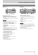
2 - Names and Functions of Parts Front panel SERIES 102i SERIES 208i 1 SIG indicators 8 1-2 input jacks These light green when signals (of at least -32 dBFS) are input. 2 GAIN knobs Use to adjust the input levels of the input jacks. 3 PEAK indicators These light red when signals are about to distort (-1 dBFS or higher). Adjust these so that the PEAK indicators do not light red. 4 USB indicator This indicator shows the status of the unit by lighting, blinking and turning off.
2 - Names and Functions of Parts Rear panel SERIES 102i SERIES 208i r Kensington Security Slot t WORD IN/OUT connectors (SERIES 208i only) d OPTICAL IN (S/MUX) connector(s) These BNC connectors are for the input and output of word clock signals. Word clock signals of 44.1, 48, 88.2, 96, 176.4 and 192 kHz can be input and output. ATTENTION If a digital system has multiple word clock masters, serious problems, including damage to equipment, could occur.
3 - Installation System requirements Check the TEAC Global Site (http://teac-global.com/) for the latest information about supported operating systems. Apple iOS devices Supported operating systems Apple device running iOS 10 or later Windows Supported audio drivers Supported operating systems Windows Windows 10 32-bit Windows 10 64-bit Windows 8.1 32-bit Windows 8.
3 - Installation Installing the dedicated software 5. Read the contents of the License Agreement, and select “I accept the agreement” if you agree to the terms. Then, click the “Next” button. 6. Next, click the “Install” button. 7. When the Windows security screen appears, click the “Install” button to start installation. 8. The following screen appears when installation has completed. Click the “Finish” button. To use this unit, a dedicated software must be installed on a computer.
3 - Installation Installing the Mac dedicated software 5. Click the “Read License” button and check the contents of the Software License Agreement. If you agree to the contents of the license, click “Agree”. Then, click the “Next” button. 6. Next, click the “Install” button to start installation. 7. The following screen appears when installation has completed. Click the “Close” button. NOTE ii Install the Mac dedicated software on the computer before connecting the unit to it with the USB cable.
3 - Installation When the ““SERIES_102i_208i_Installer.pkg” can’t be opened because it was not downloaded from the Mac App Store. Are you sure you want to open it?” security warning message appears, click the “Open” button. Changing the Gatekeeper setting The Gatekeeper setting can be changed using the “Allow applications downloaded from:” item on the “General” page of the “Security & Privacy” pane of the System Preferences.
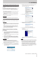
4 - Preparation Connecting the power Changing the outlet plug Use the included AC adapter (PS-P1220E) to connect a power supply to the unit as shown below. Power outlet NOTE When purchased new, the included PS-P1220E AC adapter for the unit has an outlet plug (A) already attached. There should be no need to change the plug. 1. Move the knob (1) on the PS-P1220E AC adapter in the direction of the arrow and remove the plug (A). 2.
4 - Preparation Connecting other equipment This is an example of SERIES 208i connections. Precautions before making connections oo Carefully read the operation manuals of the devices to be connected and then connect them correctly. oo Before making connections, turn this unit and all equipment to be connected off (standby). oo If possible, install all connected devices so that they are powered from the same AC power supply line.
4 - Preparation microphone that requires phantom power. Setting the switch to +48V when a dynamic mic or other device that does not require it is connected could damage this unit and connected equipment. ii Supplying phantom power to some ribbon mics could break them. If you are unsure, do not supply phantom power to a ribbon mic.
5 - Using the Settings Panel Opening the Settings Panel MIXER page You can use the Settings Panel to make settings for the various functions of this unit. Open the Settings Panel in the following manner. NOTE The Settings Panel cannot be used with an iPad or other iOS device. Windows oo From the Start menu select “SERIES 102i_208i” under “TASCAM”. Mac oo On the Launchpad, click SERIES 102i_208i.
5 - Using the Settings Panel 2 COMPRESSOR area When the input volume exceeds the THRESHOLD level, the input volume is compressed, reducing output volume variation. For example, by reducing the levels of sounds that are high level, lower level sounds become relatively louder, creating a more even volume level throughout and a more sustained sound. (see “COMPRESSOR display area overview” on page 15) Activate the Select button of a channel to make compressor settings for it.
5 - Using the Settings Panel COMPRESSOR display area overview REVERB display area overview When the input volume exceeds the THRESHOLD level, the input volume is compressed, reducing output volume variation. For example, by reducing the levels of loud sounds, lower level sounds become relatively louder, creating a more even volume level throughout and a more sustained sound. This effect adds reverberations to the original sound.
5 - Using the Settings Panel Channel Mixer details 5 COMP button Use these to turn the compressor on/off for each channel. Click the COMP button to activate the compressor. The COMP button will light and the compressor settings shown in the COMPRESSOR section will be applied. 6 PRE/POST buttons Set whether the signal sent to the AUX bus is pre-fader or post-fader. The selected button lights. Status Meaning PRE button unlit POST button unlit (default) The signal is not sent to the AUX bus.
5 - Using the Settings Panel 0 Pan slider Use to adjust the stereo positions of the signals input to each channel. Drag the pan slider left or right to adjust the stereo position. While dragging, the adjusted position is shown above the channel level meter (w). The value is L20 when set all the way to the left, R20 when set all the way to the right and C when centered. Setting range: L20 - L1, C (default), R1 - R20 The pan slider appears blue when centered (C) and yellow at all other positions.
5 - Using the Settings Panel Output adjustment section 3 AUX MASTER 1/REVERB knob and indicator Use this to adjust the send master level of the signal sent to the AUX 1 bus and reverb effect. Range: -inf. to 6 dB (default: 0 dB) Drag the 1/REVERB knob up or down to adjust the send level. While dragging, the value being adjusted is shown below and to the right of the 1/REVERB knob. The indicator lights blue at levels of 0 dB or less and yellow at levels from 0 dB to 6 dB.
5 - Using the Settings Panel LINK button overview When a LINK button on the MIXER page is turned on/off, the settings differ according to whether the stereo link is on or off. The details of the settings are as follows.
5 - Using the Settings Panel INFORMATION page NOTE ii When the unit and the computer are not connected, “No Device” is shown for the “Firmware Version” and “Device” items. ii When the 2 Sample Clock Source item is set to “Internal”, the Clock Source Status item will appear dimmed as “----------”. 2 Sample Clock Source Use this to set the sampling clock source. Option INTERNAL 1 Status display area This shows the current status of the unit.
5 - Using the Settings Panel ROUTING page SERIES 208i options Option Meaning INPUT 1 INPUT 2 Output signals as Analog/Digital Input 1-4. INPUT 3 INPUT 4 OPTICAL A1 OPTICAL A2 SERIES 102i Settings Panel ROUTING screen OPTICAL A3 OPTICAL A4 OPTICAL A5 Output signals as Analog/Digital Input 5-12.
5 - Using the Settings Panel Monitor Control screen (SERIES 208i only) On this screen, you can assign the Master and AUX bus outputs to eight analog outputs, and make settings for each output channel, including monitor speaker selection and level adjustment for Small, Medium and Large types. The set output channels and output levels, however, are only effective while the Monitor Control screen is open. Returning to the previous screen will disable these settings.
5 - Using the Settings Panel Initializing the Settings Panel Select this to reset all settings in the Settings Panel. ATTENTION Depending on the input signal level, sudden loud sounds could be output unexpectedly. We recommend initializing settings when no sound signals are being input from instruments or playback devices. Resetting the reverb settings Select this to reset the settings in the REVERB section on the MIXER page. ATTENTION After resetting, you cannot restore the previous settings. 1.
5 - Using the Settings Panel Using the SceneMemory menu Use the “SceneMemory” menu to save the current Settings Panel settings in a scene memory or to initialize those settings. SceneMemory1-10 items Use to save the current Settings Panel settings as a scene memory. Ten scene memories have been prepared in advance. Initialize Memory item Use to reset all scene memories to their default values. See “Resetting all scene memories” on page 26 for details.
5 - Using the Settings Panel Loading Settings Panel settings You can change the current Settings Panel settings by loading settings stored in a scene memory. ATTENTION Depending on the settings of the saved scene memory, sudden loud sounds could be output. We recommend loading settings when no sound signals are being input from instruments or playback devices. 1. Open the “SceneMemory” menu from the menu bar, and click the name of the scene memory to be loaded to open a submenu. 2.
5 - Using the Settings Panel Resetting all scene memories You can reset the 10 scene memories to the default values. ATTENTION After resetting, you cannot restore the previous settings. 1. Saving Settings Panel settings to the unit You can transfer the current Settings Panel settings to the unit. 1. In the menu bar, open the “SceneMemory” menu, and click “Save into the unit”. In the menu bar, open the “SceneMemory” menu, and click “Initialize Memory”. Windows version Windows version Mac version 2.
5 - Using the Settings Panel Notification function If the computer you are using is connected to the Internet, notifications might appear when the Settings Panel is launched. NOTE Put a check in the “Do not show the same message again” checkbox to prevent the same message from being shown the next time it is launched.
6 - Application Guide In this chapter, we explain how to set some audio applications for use with this unit. DAW software macOS and iTunes 1. Open the “Utilities” folder in the “Applications” folder, and double-click “Audio MIDI Setup”. Then open the “Audio Devices” window. 2. Click “SERIES 102i” or “SERIES 208i” to select it. Then, while right-clicking or control-clicking it, click “Use this device for sound output” in the pop-up menu that appears.
7 - Standalone Mode Overview oo This unit will operate in standalone mode if it is turned on when it is not connected to a computer by USB. oo You can use this unit as a mic preamp and to monitor input signals. This function is convenient when you want to practice an instrument without recording, for example.
8 - MIDI Implementation Chart MIDI Implementation Chart Function Transmit Recognize When power on × × Settable × × When power on × × Messages × × Thru Altered .................... Range × × Thru Note on × × Note off × × Polyphonic × × Channel × × Pitch bend × × Thru Control change × × Thru × × Basic channels Mode Note number Velocity Aftertouch Program change Setting range System exclusive System common System real-time Other ....................
9 - Troubleshooting Please read this chapter if you are unable to use the unit properly even after setting it following the procedures in this manual. If you are still unable to resolve your problems please contact TASCAM customer support with the following information about the operating environment and details about the trouble.
9 - Troubleshooting Sound breaks up or there is noise. The processing load on the computer causes sound to break up and noise to occur. Here are some methods to reduce the load on the computer. 1. A wireless LAN and software running in the background, including antivirus software, regularly put processing loads on the computer, which can cause sound to break up and other noise. Stop wireless LAN transmission, antivirus software and other software running in the background when using this unit. 2.
10 - Specifications General Analog outputs Sampling frequencies Monitor outputs (balanced, LINE OUT 1-2) 44.1, 48, 88.2, 96, 176.4, 192 kHz Quantization bit depth 24-bit Inputs and outputs Analog inputs Mic inputs (balanced) SERIES 102i: 1-2 SERIES 208i: 1-2, 3-4 (when the input switch is set to MIC/LINE) Connector : XLR-3-31 equivalent (1: GND, 2: HOT, 3: COLD) Input impedance: 1.5 kΩ Rated input level: -64 dBu (0.0005 Vrms, GAIN knob at maximum) -6 dBu (0.
10 - Specifications Audio performance Mic amp EIN (equivalent input noise) -129 dBu or lower Frequency response MIC/LINE IN At 44.1/48 kHz, 20 Hz – 20 kHz: +0 dB/-0.4 dB (JEITA) At 88.2/96 kHz, 20 Hz – 40 kHz: +0 dB/-0.8 dB (JEITA) S/N ratio 109 dB (MIC/LINE IN, GAIN knob at minimum, 20 kHz SPCL LPF + A-Weight) 110dB (LINE OUT, MONITOR knob at maximum, 20 kHz SPCL LPF + A-Weight) THD + N SERIES 102i 0.0016% (MIC IN, 1 kHz sine wave, GAIN knob at minimum, 20 kHz SPCL LPF) 0.
10 - Specifications General Power DC12V AC adapter (PS-P1220E) Power consumption SERIES 102i: 7.2 W SERIES 208i: 14 W Dimensions SERIES 102i: 186 × 65 × 160 mm (width × height × depth) SERIES 208i: 296 × 65 × 160 mm (width × height × depth) Weight SERIES 102i: 1.1kg SERIES 208i: 1.
10 - Specifications Dimensional drawings 160mm SERIES 102i 186mm 65mm 160mm SERIES 208i 296mm 65mm oo Illustrations in this manual might differ in part from the actual product. oo Specifications and external appearance might be changed without notification to improve the product.
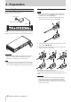
ADC ADC ADC ADC Receiver IN 1 4 BAND EQ COMP Mixer True Bypass P PHASE You are able to use all optical inputs at 44.1/48kHz You are only able to use No.1 to No.4 optical inputs at 88.2/96kHz You are only able to use No.1 and No.2 optical inputs at 172.
TEAC CORPORATION Phone: +81-42-356-9143 1-47 Ochiai, Tama-shi, Tokyo 206-8530 Japan TEAC AMERICA, INC. https://tascam.jp/jp/ https://tascam.com/us/ Phone: +1-323-726-0303 10410 Pioneer Blvd. Suite #1 and #4, Santa Fe Springs, California 90670, U.S.A. TEAC UK Ltd. https://www.tascam.eu/ TEAC EUROPE GmbH https://www.tascam.