BT-320 OPERATING AND MAINTENANCE INSTRUCTIONS 10K, 24K, 38K CRYOSTORAGE SYSTEMS WITH KRYOS CONTROLLER REVIEW AND UNDERSTAND ALL SAFETY PROCEDURES IN FORM # tw-10 P/N 7950-8052 BEFORE ATTEMPTING TO INSTALL, OPERATE OR PERFORM MAINTENANCE ON THIS CRYOSTORAGE SYSTEM. DO NOT ATTEMPT TO USE OR MAINTAIN THIS UNIT UNTIL YOU READ AND UNDERSTAND THESE INSTRUCTIONS. DO NOT PERMIT UNTRAINED PERSONS TO USE OR MAINTAIN THIS UNIT.
Text Format Notation In this owner’s manual we use some special text formats to denote certain portions of the system. These are listed below: • • • • Menu is indicated in ALL CAPS BOLD. Actual Menu Choices are indicated in ALL CAPS. Start Fill and Stop Fill sensor are indicated in ALL CAPS ITALICS. Specific Menu Descriptions under a main category are listed in Italics.
Note: Units are supplied with TaylorWharton approved controllers. If other liquid level controllers are used, please contact Taylor-Wharton before putting the refrigerator into service. Electrical Electrical Shock Can Kill – the liquid level controllers used with these refrigerators operate from 24VAC. However, the external transformer does have a 110/220VAC primary. Do not attempt any service on these units without disconnecting the electrical power cord.
Liquid nitrogen at atmospheric pressure weighs 1.78 lb./liter (0.8 kg/liter). To ensure you are not exceeding the capacity of the cryostorage system, calculate the weight of the quantity of liquid nitrogen in your unit and subtract the result from the Total Allowable Capacity Weight found in the specifications section of this publication.
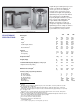
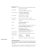
KRYOS Specifications Configurations: Designed exclusively for the Taylor-Wharton CryoStorage Systems (10K, 24K and 38K Power Supply: 24VAC, 40 VA – Standard 16.
Please use the packing list to check off each item as the system is unpacked. Inspect for damage. Be sure to inventory all components supplied before discarding any shipping materials. If there is damage to the system during transit, be sure to file proper claims promptly with the carrier and insurance company. Please advise Taylor-Wharton of such filings. In case of parts or accessory shortages, advise Taylor-Wharton immediately.
from opening when the system is in operation, the liquid nitrogen supply system must be protected by a pressure relief device that will open when the pressure at the inlet to the refrigerator(s) is approximately 22 psig (1.5 bar/152 kPa). Never install the supply system pressure relief device onto a liquid service line. Installation KRYOS Control Field Installation 1. Unplug power from old unit 2. Close liquid nitrogen supply at valve 3. Remove 4 phillips head screws from controller face escutcheon 4.
WARNING INLET PRESSURE MUST NOT EXCEED 22 PSIG (1.5 BARL HIGHER PRESSURES COULD RESULT IN DAMAGE TO EQUIPMENT AND/OR SUFFICENT DEPETION OF OXYBEN IN THE ATMOSPERE TO CAUSE DIZZINESS, UNCONSCIOUSNESS OR EVEN DEATH. DO NOT REMOVE THIS LABEL DECAL PART NO. R23K-9C42 Figure 2. Warning Label (R23K-9C42 Filling the Refrigerator (Initial Fill) The 10K and 24K units using the KRYOS controller come preset from the factory to operate. For the 38K unit, refer to the Installing the Controller section in this manual.
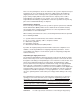
Main Control The “brain” for the control system “talks” to the interface unit and makes all decisions regarding liquid levels, temperatures, valve opening/closing, etc. It is either housed in a separate box, or located away from the Interface Panel. Sensor Assembly A standard 7+1 thermistor assembly, includes the Freeze-Guard over-fill sensor. Optional 4 thermistor, or 8 thermistor sensor assembly can be ordered. The 4 thermistor assembly maintains the liquid level between 2 middle sensors.
OPERATION Operating Parameters When materials are immersed in liquid nitrogen, they will assume the temperature of the liquid -196ºC (-320ºF). When material is stored in the vapor phase over the liquid, the liquid nitrogen is still a very cold refrigerant, but the refrigerator’s interior temperature increases somewhat as product is stored higher over the liquid.
NOTE: Temperature Gradient Suppression Systems are specifically designed for use in vapor phase applications and will be of little value when liquid phase storage is used. Temperature Gradient Suppression System Most Taylor-Wharton CryoStorage units include a Temperature Gradient Suppression System.
When removing ICS racks to retrieve product, protect the labels, plastic, and electronic areas of the refrigerator from liquid nitrogen that may spill from the rack inserts. These parts of the refrigerator are subject to damage from the extreme low temperature of the refrigerant. If an alternate platform is supplied with your inventory control system, the liquid phase platform in the bottom of your refrigerator may need to be removed to accommodate your inventory control system platform.
CONTROL OPERATION This section of the operating manual is for Taylor-Wharton approved equipment that uses the KRYOS controller. For models that use the Mark IL controller refer to operating manual TW-303, P/N 7950-8303, for the Mark 3 controller refer to operating manual TW-291, P/N 7950-8291, for the Mark 2L controller refer to operating manual TW-290, P/N 7950-8290. Introduction The KRYOS temperature and LN level controller is designed for easy operation and 2 uninterrupted, reliable service.
Main Display Screen The main display screen consists of 4 lines of information. Line 1: Displays the current status of the control. It indicates if all systems are normal or if any errors have been detected. Error messages disappear when the error is corrected. Line 2: Displays the level sensing in the control. If the 7 thermistor or 8 thermistor assembly is being used, the control will indicate actual liquid level in the freezer.
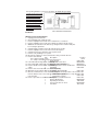
DISPLAY MENU MAP 4.3.3 User Access Logs 1. Temperature 4.4 Temperature Logs 1.1 Thermocouple Select 4.4.1 Thermocouple #1 Log Rate 2.2 Calibrate Temperature 4.4.2 Thermocouple #2 Log Rate 2.3 Test Temperature System 4.5 Erase Logs 2. Level Sensing 4.5.1 Erase System Logs 2.1 Test Level Sensors 4.5.2 Erase Error Logs 2.2 Sensor Positions 4.5.3 Erase Temperature Log #1 2.3 Sensor Positions 4.5.4 Erase Temperature Log #2 2.3.1 Start Fill 5. Security 2.3.2 Stop Fill 5.1 Power-On Password 2.4 Sensor Type 5.
est part of the chamber (worst case temperature). Factory installation includes one thermocouple inside of the sensor tube at an elevation to match the height of standard racks. A second Type T thermocouple may be added to monitor another location inside the chamber. Both thermocouples can be activated/deactivated through the menu system. (MENU, 1,1) Calibrate Temperature KRYOS provides easy calibration of the thermocouples. To calibrate, the user should enter the menu system (MENU, 1,2).
for open, a “G” for gas or an “L” for liquid. This is an easy means to tell if sensors are in or out of liquid or if a new sensor assembly is needed (open sensors). Set Sensors Offset A sensor offset can be set through the menu system of the control (MENU, 2, 2). The offset is used if the sensor assembly is raised off the floor of the freezer and the user wants to read the actual liquid level on the display. An example of this would be a STOP FILL setting of 23” and a START FILL setting of 20”.
condition. The red light will continue to flash until all errors are corrected. It can not be disabled without disconnecting the power supply. The remote alarm will be activated if the power supply is interrupted. The High Temperature Alarm for Thermocouple #1 can be set through the menu system (MENU, 3, 1). This alarm is activated if the temperature rises above the designated temperature. The alarm temperature can range from 0ºC to -190ºC. It can also be disabled.
Logging The on board memory logging function is one of the most powerful and useful features of the KRYOS control. It provides a historical record for not only your freezer but also a complete record of the environment in which specimens were stored. Four separate logs are kept in the control: 1. System log – System logs are events that occur in the system such as lid opening/closing, LN filling Quick-Chill, Defog, etc. 2 , 2. Error log, - Error logs are off-normal conditions detected by the system. 3.
Dump Logs Dump SYSTEM LOGS is accessible through the menu system of the control (MENU, 4,1,1). This option sends data from the system logs to the serial port of the freezer. When this option is chosen, the display reports how many system logs are in the system. While the data is being sent to the serial port, it can be paused or completely cancelled through the menu system. DUMP ERROR LOGS is accessible through the menu system of the control (MENU, 4,1,2).
closings. The choices are ENABLE or DISABLE. Records in the system log. USER ACCESS LOGGING is accessible through the menu system of the control (MENU, 4,3,3). This menu choice turns on/off the logging of user access codes, which are requested when the lid is opened. Records in the system log. Temperature Logs Temperature Logging Rates for thermocouple #1 (T/C #1 LOGGING) and thermocouple #2 (T/C #2 LOGGING) are accessible through the menu system of the control MENU, 4,4,1 or MENU, 4,4,2).
password by typing in 9999 when asked for the password, KRYOS will display an 8digit number. Call your distributor or Taylor-Wharton with the 8-digit number to obtain a unique 8-digit number to type into the control. When this number is entered, the passwords will be cleared and full access to the control is restored. User Options The user options menu choice covers all other control settings not already covered.
Lid Switch Setup LID SWITCH SETUP can be through the menu system of the control (MENU 6,2,2,2). This option enables or disables the lid switch. Auto Defog The AUTO DEFOG (MENU, 6,2,2,3) feature provides a burst of gaseous N to the 2 freezer to clear the fog when the lid is opened. This is activated through the lid switch. If the lid switch is deactivated this feature will be disabled. The choices for auto defog are disabled through 90 seconds.
Control Range CONTROL RANGE can be accessed through the menu system of the control (MENU, 6,2,3,2,2). KRYOS maintains a temperature range around the user-selected temperature. A tighter range maintains a temperature very close to the selected temperature at the cost of greater LN usage. A broad range provides more temperature variability 2 but the LN usage is less. The range can be varied from +1º to +15ºC above and 2 below the selected temperature.
because the level has reached the STOP FILL sensor, the display will flash “Check” and the control will check the validity of the signals received from the sensor assembly. The splash-guard check occurs for 20 seconds and the bottom line of the display indicates this by flashing “Check”. Display Brightness DISPLAY BRIGHTNESS can be set through the menu system of the control (MENU, 6,3). This option changes the intensity of the display. The possible choices are 25%, 50%, 75% and 100%.
NOTE: Ice or frost in the sensor tube may restrict the movement of sensor probes in the tube. Do not pull excessively on the sensor wiring while attempting to change sensor position. It may be necessary to remove the sensor tube from the container and allow it to thaw before the sensors can be repositioned Defrosting Your K-Series Cryo-Storage System All liquid nitrogen storage systems are subject to ice and frost buildup over time.
WARNING: Never use chlorine-based disinfectants to clean a CryoStorage System. Normal Evaporation Rate (NER) Test Nitrogen consumption is an accumulation of all system components and userintroduced evaporation. The storage chamber is a double walled, vacuum insulated vessel and contributes to the daily consumption of liquid nitrogen. The liquid nitrogen supply vessel and transfer hose also contribute greatly to the daily consumption rate.
access to its back panel connection. At the completion of maintenance or repairs, reattach the electrical connection wiring to the controller. To install the controller, install the electrical supply connections panel to the back of the refrigerator. Feed the wiring harness from the electrical supply connections panel to the front of the refrigerator and through the opening to where the controller will be mounted. Attach the electrical supply connections to the controller board.
the sensor tube and remove the sensor leads from the plug. Making Adjustments to the KRYOS Sensor Assembly The factory settings for the KRYOS control system are as follows: • • • • Low Level Alarm = 2 (Always 1” below the start fill) Start Fill Sensor = 3 Stop Fill Sensor = 6 High Level Alarm = 7 (Always 1” above the stop fill) The sensor assembly is pushed to the bottom of the refrigerator as delivered from the factory. If adjustments need to be made, the following procedure will simplify the process.
The sensor assembly is pushed to the bottom of the refrigerator as delivered from the factory. If adjustments need to be made, the following procedure will simplify the process. • Determine the range of the LN level in the refrigerator (i.e. Start Fill = 9; Stop Fill 2 = 12) • Determine the appropriate offset by subtracting 2 from the Start Fill. (i.e. Offset = 9-2=7) • Set the sensor assembly so that the very bottom of the assembly matches the desired offset.
connection to the controller board. At the completion of maintenance or repairs, install the controller using the procedure outlined for your refrigerator model in the Removing/Installing the Controller section. Controller Electrical Tests If a controller is removed from the refrigerator for service, the liquid refrigerant level must be maintained manually to protect stored product. The fill solenoid valve will be inoperative with the controller removed.
TROUBLESHOOTING In addition to the above, an alarm condition may be triggered by an exceedingly long fill mode. The key to troubleshooting your CryoSorage system is to determine which component in the system is the source of the problem. Determine if the problem is occurring in any of the following subsystems: Supply Vessel, Transfer Line, Power Source, Temperature, Level Sensing, Security, Lid Switch, Solenoid Valve, Control Display, Alarm System, Communications.
LIQUID. NOTE THAT THE low level alarm ceases, fill solenoid valve is still open. Control is flashing FILLING. • • • • • Manually press STOP button and note that the fill solenoid valve closes. Press FILL button to re-open fill solenoid valve. Continue to lower the sensor until the STOP FILL thermistor is immersed in the LN . Thefill should stop after a confirming (CHECK) SPLASH GUARD period. 2 Simulate an over fill by lowering the next thermistor into the LN .
Temperature reading 10 to 20 degrees warm. 1. Make sure sensor tube is breathing. If Ice build up is a problem in a humid environment or if you have a clear polycarbonate sensor tube, the thermocouple may be attached to the outside of the sensor tube with nylon wire ties. Tuck thermocouple out of harms way on side or back of sensortube. Do Not attach thermocouple to fill tube. • Prepare an ice water slurry with crushed ice and tap water. Dip or pour LN into a 2 styrofoam cup to prepare an LN bath.
should direct vent gases out the back of the lid and away from the controller. • Adjust lid hinges and/or replace gasket. 2. Check seal between top of tub and beige cabinet top. The black gasket should prevent venting under the cabinet top. 3. Check seal around sensor wires. Tape or spray foam this gap if needed. Message “Please Wait” A circuit board malfunction has occurred. Call your authorized Taylor-Wharton agent for assistance.
above the STOP FILL thermistor assignment. For this reason START FILL cannot be assigned to thermistor number 1. Similarly, STOP FILL cannot be assigned to thermistor number 7. The factory installs this seven thermistor assembly all the way to the floor of the sensor tube, which positions thermistor number 1 one inch above the floor (i.e.; the first thermistor is offset from the floor zero inches). 1.
REPLACEMENT PARTS Refrigerator Parts (10K/24K) 10K Cabinet, Back, Panel ................................................................................................ R10K-9C35 Cabinet, Front, Panel ................................................................................................ R10K-9C33 Cabinet, Side, Panel .................................................................................................. R10K-9C34 Cabinet, Top, Panel (old style 24K w/12 o’clock Fill Tube = R23K-9C10) ..
Fully Auto -MOWDEN MARK 1 -GE MARK 2 -PCR CONTROLLER 5140-1128 5140-1145 5140-1131 SENSOR ASSEMBLY R06K-9C44 5140-1147 R08K-9C49 THERMOCOUPLE R06K-9C46 N/A R08K-9C51 REMOTE ALARM PLUG R06K-8C20 R06K-8C20 NOTE 1 1 R23K-9C96 R23K-9C96 R23K-9C96 SENSOR TUBE SENSOR TUBE PLUG R10K-9C69 R10K-9C69 R10K-9C69 TRANSFORMER N/A 5140-1146 N/A ELECTRIC PANEL R06K-9C25 5140-1148 R08K-9C47 LID SWITCH N/A 5160-1042 N/A CABLE, LID SWITCH N/A R23K-9C71 N/A PLUMBING ASSEMBLY N/A R23K-8C61 R17K-8C61 2 R06K-9C61 6999-9021 R08
Fill in top section at installation. Copy this form each time service is required. Fill bottom section with service notes to keep a complete log of each freezer service and maintenance history.