Laser Pak III Part Number LP3000 Do not attempt to use or maintain these units until you read and understand these instructions. Refer to the TaylorWharton’s Safety First booklet (TW-202) for handling cryogenic material. Do not permit untrained persons to use or maintain this equipment. If you do not understand these instructions, contact your supplier for additional information.
WARNING Safety Precautions for Liquid Oxygen Safety Precautions for Liquid Nitrogen INTRODUCTION System Description PIPING CIRCUITS Fill and Vent Circuits Express Fill Circuit Pressure Building Circuit Gas Withdrawal Circuit Economizer Circuit Safety Devices Instrumentation Circuits OPERATION Receiving Inspection Handling Determining Proper Fill Weight Filling by Pressure Transfer Filling by Pump Transfer Withdrawing Gas Withdrawing Liquid Changing Gas Service MAINTENANCE Leak Test Globe Valves Regulators I
WARNING The following safety precautions are for your protection. Before installing, operating, or maintaining this unit read and follow all safety precautions in this section and in reference publications. Failure to observe all safety precautions can result in property damage, personal injury, or possibly death. It is the responsibility of the purchaser of this equipment to adequately warn the user of the precautions and safe practices for the use of this equipment and the cryogenic fluid stored in it.
spilled liquid. If clothing should be splashed with liquid oxygen or otherwise saturated with the gas, air out the clothing immediately, removing it if possible. Such clothing will be highly flammable and easily ignited while the concentrated oxygen remains, and should not be considered safe for at least 30 minutes.
INTRODUCTION This manual provides information for the operation and maintenance of Taylor-Wharton's Laser Pak III transportable cryogenic gas supply system. The Laser Pak III is designed for applications requiring nitrogen, argon, or oxygen gas at pressures and flow-rates higher than possible with traditional pallet base cryogenic vessels. The Laser Pak III is capable of delivering gas at a continuous rate of 2,000 standard cubic feet per hour while maintaining a supply pressure exceeding 350 psig.
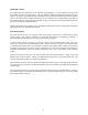
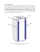
PIPING CIRCUITS The following paragraphs describe the operation of the piping circuits of the system. The descriptions refer to the main components of each circuit and are grouped by function. Reference the piping schematic below and in the general arrangement drawing for the component designations. These component and circuit descriptions should be understood before attempting operation.
Fill and Vent Circuits The liquid valve (V-7) communicates with the bottom of the vessel. A stainless steel tag labeled “LIQUID” identifies the valve and the liquid connection (CN-4). Liquid is added or removed from the vessel through this connection and valve. The vent / trycock valve (V-4) is attached to a vertical tube in the upper portion of the vessel. The open end of the tube is positioned at 90% liquid level based on the vessel volume.
Express Fill Circuit The Express Fill circuit may be used for filling from the Taylor-Wharton Express Truck or for top filling by a cryogenic pump. The pump / top fill valve (V-1) is a quarter-turn ball valve permitting filling of the vessel. A check valve (CV-1) prevents product from escaping should the pump / top fill valve be opened inadvertently. A fill stop valve (FSV-1) within the vessel prevents over filling.
Pressure Building Circuit The pressure building circuit serves to build pressure after filling the vessel. The circuit is also used to ensure sufficient driving pressure during high product withdrawal periods. Opening the pressure building circuit valve (V-3) permits the circuit to function. A stainless steel tag labeled “P.B.” is attached to the valve. When the pressure inside the vessel drops below 450 psig, the pressure building regulators (PVC-1) begin to open.
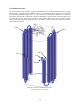
Gas Withdrawal Circuit The gas withdrawal circuit vaporizes cryogenic liquid and warms it to ambient temperatures for use in the final application. Opening the gas withdrawal valve (V-5) allows liquid, driven by the pressure within the vessel, to flow through the vaporizer (VC-1). The vaporizer uses heat from the ambient air to convert the liquid into a gas and warm it. Should the vaporizer be damaged or require repair the vaporizer isolation valve (V-2) may be closed to prevent loss of product.
Economizer Circuit The economizer circuit reduces product loss due to normal evaporation of the liquid within the vessel. The economizer regulator (PVC-2) opens when the pressure within the vessel exceeds 475 psig. This allows gas from the top of the vessel to flow into the vaporizer circuit. Provided that gas from the vaporizer is being withdrawn for use, the vessel pressure will be reduced. The primary safety valve (SV-1) will be prevented from opening, avoiding product loss.
Safety Devices The Laser Pak III features relief devices to prevent over pressurization of the vessel, piping, and vaporizers. A primary relief valve (SV-1) relieves pressure when it exceeds 500 psig. The valve reseats when pressure drops below this point. In addition, the primary relief valve is supported by a secondary relief device consisting of a rupture disc (R-1) that will burst at a pressure of approximately 750 psig.
Instrumentation Circuits The instrumentation consists of a pressure gauge and differential pressure gauge. The pressure gauge (PI-1) displays the inner vessel pressure in pounds-per-square-inch and kilopascals. The differential pressure gauge measures the difference in pressure between the top and bottom of the vessel. Product within the vessel creates a higher pressure at the bottom of the vessel than at the top. Readings on the differential pressure gauge are in inches of water.
OPERATION These instructions are for operators experienced with cryogenic equipment. Before operating the system, become familiar with the safety precautions in this manual and in reference publications. Study this manual and the general arrangement drawing located in the back of this manual thoroughly. Know the location and function of all system components. Receiving Inspection Freight and damage claims are the customer’s responsibility.
CAUTION: Follow the safety precautions at the beginning of this manual. Accidental contact with liquid or cold gas can occur during filling. A cryogenic transfer hose equipped with a relief valve and dump valve should be used to connect the Laser Pak III to the liquid source. Follow the instructions below to fill by pressure transfer: 1. Determine the proper fill weight following the instructions in the previous section. 2. Visually inspect the Laser Pak III, transfer hose, and bulk tank piping.
Withdrawing Liquid Attach a transfer hose from the receiver vessel to the Laser Pak III liquid connection (CN-4) and open the adjacent liquid valve (V-7). The pressure in the container will drive liquid product out through the valve as long as the container pressure exceeds that of the receiver. Changing Gas Service The Laser Pak III may be used for argon, oxygen, or nitrogen service. Follow these steps to properly change gas service: 1. Safely empty all liquid from the container. 2.
MAINTENANCE Routine inspections of the system are recommended. The need for maintenance usually becomes apparent from inspection and indications of improper operation. Typical trouble indications include leakage from valves or piping connections and excessive venting through relief valves. Keep a permanent log of all inspections and repairs performed. Such a log can be valuable in evaluating performance and scheduling maintenance.
Regulators The two pressure building regulators may be adjusted without removal from the system. The following procedure describes the process: 1. Fill the container with liquid product. 2. Open the pressure building valve and allow the container pressure to stabilize for about an hour. Note the pressure. 3. Adjust the screw on the top of the regulator to raise of lower the pressure to the desired point.
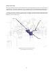
9. When reinstalling the pressure building regulators on the system, orient the regulator so the flow arrow points toward the pressure building valve. Adjustment of the economizer regulator should be accomplished with the regulator removed from the system. The regulator bench adjustment fixture shown above should be used. 1. Leak test joints between the high pressure cylinder regulator and the dump valve. Joints must be leak free before proceeding. 2. Close the on/off valve. Open the dump valve. 3.
3. Condensation may form on the container. Note that some icing or condensation is normal around the piping connections of the vessel. Condensation may also occur on the vessel outer surface as a result of high humidity. 4. The relief valve will open continuously until the container is empty. If a loss of vacuum integrity is suspected, the container’s normal evaporation rate (NER) should be checked. The test procedure explained below measures the actual product lost over time. 1.
Trouble-Remedy Guide Trouble Possible Cause Remedy 1. a. a. Thaw out valve or replace if necessary. b. Replace disc. c. Leak test and repair piping. d. Adjust regulators. Replace if necessary. Low operating pressure. b. c. d. e. 2. 3. 4. Excessive system pressure. Leaking relief valve (RV). Ruptured pressure vessel rupture disc (BD). Safety valve leaking or frozen open. Safety disc ruptured. Piping leaks to atmosphere. Pressure building regulator or economizer regulator malfunction.
Replacement Parts Order replacement parts from Taylor-Wharton Customer Service at 1-800-898-2657. Refer to the piping circuits section to identify the components.
APPENDIXES Appendix 1 - Laser Pak III General Arrangement 23
4075 Hamilton Blvd. Theodore, Alabama 36582 U.S.A. Telephone (251) 443-8680 Fax (251) 443-2250 In U.S.