BT-235D VJ Series CO2 / N20 Bulk Storage Tanks Do not attempt to use or maintain these units until you read and understand these instructions. Refer to the TaylorWharton’s Safety First booklet (TW-202) for handling cryogenic material. Do not permit untrained persons to use or maintain this equipment. If you do not understand these instructions, contact your supplier for additional information.
TABLE OF CONTENTS SAFETY PRECAUTIONS FOR CARBON DIOXIDE ........................................................................ 3 SAFETY PRECAUTIONS FOR NITROUS OXIDED ......................................................................... 4 INTRODUCTION .................................................................................................................................. 5 PROPERTIES OF CARBON DIOXIDE ............................................................................................
SAFETY PRECAUTIONS FOR CARBON DIOXIDE WARNING: Carbon Dioxide can cause asphyxiation and death in confined, poorly ventilated areas. Cold Carbon Dioxide gas can cause severe frostbite to the eyes or skin. Do not touch frosted pipes or valves. If accidental exposure occurs, consult a physician at once. If a physician is not readily available, warm the areas affected by frostbite with water that is near body temperature.
SAFETY PRECAUTIONS FOR NITROUS OXIDED WARNING: The following safety precautions are for your protection. Before performing installation, operation, or maintenance procedures, read and follow all safety precautions in this section and in reference publications. Failure to observe all safety precautions can result in property damage, personal injury, or possibly death.
INTRODUCTION This manual provides information for the user to operate and maintain Taylor-Wharton Cryogenics VJSeries Carbon Dioxide Storage Vessels. These tanks are primarily intended for liquid withdrawal at a normal operating pressure between 260 psig (18 bar/1793 kPa) and 320 psig (22 bar/2206 kPa), the maximum allowable working pressure is 350 psig (24 bar/2413 kPa).
FUNCTIONAL DESCRIPTION TANK CONSTRUCTION The pressure vessel is suspended inside the vacuum jacket and insulated with perlite powder. The liquid and gas phase lines to the pressure vessel pass through the lower head of the vacuum jacket. All piping is designed to withstand the stresses caused by expansion and contraction of the pressure vessel, its support system, and the piping itself.
Instrumentation LIQUID LEVEL GAUGE (LI-1) is a differential pressure gauge that indicates tank liquid level and is calibrated for lbs/tons of CO2. PRESSURE GAUGE (PI) is a 0-600 psi gauge with 4-1/2" face. It is mounted beside the liquid level gauge. INSTRUMENT EQUALIZATION VALVE (V-7) is used to equalize the pressure between the high and low-pressure sides of the contents gauge. LIQUID PHASE ISOLATION VALVE (V-6) isolates contents and pressure gauges from the tank liquid (bottom) phase.
INSTALLATION HANDLING Tank installation is the customer's responsibility. The tank is shipped in the horizontal position and secured on wooden cradles. These cradles must be removed prior to erection of the tank. Make certain the foundation used for the tank is designed for the conditions at the installation site, and that it is suitable for the tank weight. Refer to local codes for recommended foundation specifications. Employ experienced personnel to move and install the tank.
Designing safe and effective systems for handling liquefied gases requires extensive knowledge and experience. Persons lacking the necessary skills are urged to seek help from the manufacturer. Design and consultation services are available from the Customer Service Department. WARNING: To protect the purity of the pressure vessel, all tanks are shipped with a charge of nitrogen at 20 PSIG (1.4 bar/138 kPa).
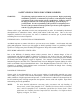
RIGGING Note: Refer to General Arrangement Drawing for Critical Weight and Dimensional Data Rigging VJ-6 TON & VJ-14 TON 10
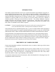
Note: Refer to General Arrangement Drawing for Critical Weight and Dimensional Data Rigging VJ-26 TON, VJ-35 TON & VJ-50 TON 11
OPERATION Normal operation of a properly installed unit requires some operator intervention. Frequent checks should be made to ensure pressure and liquid levels are within normal range. Low pressure could cause damage to the tank due to resulting liquid temperature below the design parameters of the steel in the pressure vessel. A daily inspection that includes checks for frost, leaks, low pressure, low liquid level and physical damage is recommended.
8. Loosen setscrew lock nut on BACK PRESSURE REGULATOR (PCV) and turn setscrew counterclockwise to the end of its travel counting the number of turns made. Open REGULATOR ISOLATION VALVE (V-8) to purge safety line. 9. Repeat purge procedures 2 through 8 until an acceptable product purity is achieved. 10. Reconnect the LIQUID LEVEL GAUGE (LI), open ISOLATION VALVES (V-6, V-5) and close EQUALIZATION VALVE (V-7).
maintained above this value to insure solid CO2 will not form inside the container. Before performing maintenance, components must be isolated and depressurized, or the contents must be transferred to another container so that the container pressure can be released. In addition to avoid irreparable damage to the structure of the tank, an internal tank pressure of no less than 200 PSIG (14 bar/1379 kPa) must be maintained at all times.
Refer to the Trouble-Remedy Guide in this manual for maintenance procedures. If the problem is not readily corrected, replace the gauge with a spare. Field repair and recalibration of the LIQUID LEVEL GAUGE (LI) is not recommended. Return the defective gauge to the manufacturer for repair. Include a description of difficulty encountered.
VACUUM GAUGE TUBE If the gauge tube is damaged or is suspected of giving inaccurate readings, replace it as follows: 1. Make certain that the gauge tube isolation valve is closed. 2. Unscrew the gauge tube from the valve. Use two wrenches, one on the tube, one on the valve. 3. Clean the threads and opening of the valve. NOTE: Do not use Teflon tape as a sealant on vacuum system fittings. 4. Thread the new gauge tube into the valve by engaging one thread.
Try to determine the source of leakage in cases where the casing safety device has not ruptured; visually inspect the exterior of the casing. Check the following areas in the order in which they are listed: a. Vacuum gauge tube, b. Vacuum gauge tube valve (V-3), c. Casing evacuation valve (V-4), d. Casing bursting disk (R-1), e. All liquid and gas phase lines at exit point from casing, f. Any area of the casing that might have been exposed to cryogenic liquid spray or contact.
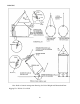
Figure 6.
RE-EVACUATION PROCEDURE After any required vacuum repairs have been completed, re-evacuate the insulation space as follows: 1. Break the seal wire and remove the pipe plug from the evacuation valve. Use two wrenches, one on the valve, the other on the plug. 2. Be sure that there is not positive pressure in the casing. If necessary, crack open the evacuation valve to relieve the pressure. 3. Check that the inner container is empty, warm, and pressurized to at least 10 psig. Refer to "Warming the Tank".
MOVING THE TANK Purge and warm tank prior to removal and shipping. The tank must not be shipped cold because the internal supports are not designed to withstand the shipping loads when the tank is cold. Before moving the tank, refer to Taylor-Wharton Cryogenics Customer Service Dept. Refer to rigging information in "Installation" section when relocating the tank. TROUBLE-REMEDY GUILD POSSIBLE CAUSES TROUBLE 1. Tank Pressure too low. a. Pressure Vessel Safety Valve leaking b.
5. 6. Leaking safety valve. Tank vacuum leak. a. Dirt or ice under valve or disc. b. Improper valve set point. c. Damaged valve seat or disc. a. Leak in Vacuum Jacket Relief Device. b. Evacuation Valve leak. c. 7. Inability to obtain desired vacuum when re-evacuating. a. Thaw out valve. Replace if necessary. b. Replace valve. c. Replace valve. a. Refer to Analyzing Vacuum b. Replace Evacuation Valve diaphragm. c. Replace faulty component. Re- d.
REPLACEMENT PARTS Order replacement parts from Taylor-Wharton, Cryogenic Equipment Plant, Theodore, Alabama or the prime manufacturer. All replacement parts must be cleaned for oxygen service before installation on the tank. If ordering from the prime manufacturer, provide the Taylor-Wharton part number and all identifying information with part being serviced. Refer to tank Flow Diagram. VACUUM-JACKETED CO2 TANKS Valve Number Description VJ-6 Part Number VJ-14 VJ-26 VJ-35 VJ-50 V-1 Ball Valve 2.
APPENDIX A: CONTENTS GAUGE CHARTS VJ-6 TON CONTENTS GAUGE CHART 260 PSIG INCHES OF WATER GALLONS TONS WEIGHT (LBS) 5 0 0 0 10 14 .06 118 15 57 .24 490 20 115 .50 997 25 177 .77 1532 30 239 1.03 2068 35 301 1.30 2603 40 363 1.57 3139 45 425 1.84 3674 50 486 2.10 4210 55 548 2.37 4745 60 610 2.64 5281 65 672 2.91 5816 70 734 3.18 6351 75 796 3.44 6887 80 858 3.71 7422 85 920 3.98 7958 90 982 4.25 8493 95 1043 4.
VJ-6 TON CONTENTS GAUGE CHART 320 PSIG INCHES OF WATER GALLONS TONS WEIGHT (LBS) 5 0 0 0 10 15 .06 128 15 62 .26 518 20 124 .52 1040 25 188 .79 1583 30 253 1.06 2126 35 318 1.33 2669 40 382 1.61 3212 45 447 1.88 3754 50 512 2.15 4297 55 576 2.42 4840 60 641 2.69 5353 65 705 2.96 5926 70 770 3.23 6469 75 835 3.51 7011 80 599 3.78 7554 85 964 4.05 8097 90 1028 4.32 8640 95 l093 4.59 9183 100 1158 4.86 9725 105 1222 5.
VJ-14 TON CONTENTS GAUGE CHART 260 PSIG INCHES OF WATER GALLONS TONS WEIGHT (LBS) 5 0 0 0 10 8 .04 71 15 58 .25 498 20 139 .6 1203 25 239 1.03 2065 30 343 1.48 2970 35 448 1.94 3875 40 552 2.39 4780 45 657 2.84 5685 50 762 3.29 6589 55 866 3.75 7494 60 971 4.20 8399 65 1075 4.65 9304 70 1180 5.10 10209 75 1284 5.56 11114 80 1389 6.01 12019 85 1494 6.46 12924 90 1598 6.91 13829 95 1703 7.37 14734 100 1807 7.
VJ-14 TON CONTENTS GAUGE CHART 320 PSIG INCHES OF WATER GALLONS TONS WEIGHT (LBS) 5 0 0 0 10 9 .04 77 15 63 .26 528 20 150 .63 1264 25 256 1.07 2150 30 365 1.53 3067 35 474 1.99 3985 40 584 2.45 4902 45 693 2.91 5819 50 802 3.37 6737 55 911 3.83 7654 60 1020 4.29 8571 65 1130 4.74 9489 70 1239 5.20 10406 75 1348 5.66 11323 80 1457 6.12 12241 85 1566 6.58 13158 90 1676 7.04 14075 95 1785 7.50 14993 100 1894 7.
VJ-26 TON CONTENTS GAUGE CHART 260 PSIG INCHES OF WATER GALLONS TONS WEIGHT (LBS) 10 6 .03 51 20 131 .57 1131 30 334 1.44 2888 40 543 2.35 4698 50 752 3.25 6508 60 961 4.16 8318 70 1170 5.06 10127 80 1380 5.97 11937 90 1589 6.87 13747 100 1798 7.78 15557 110 2007 8.68 17367 120 2216 9.59 19176 130 2425 10.49 20986 140 2634 11.40 22796 150 2844 12.30 24606 160 3053 13.21 26416 170 3262 14.11 28226 180 3471 15.
VJ-26 TON CONTENTS GAUGE CHART 320 PSIG INCHES OF WATER GALLONS TONS WEIGHT (LBS) 10 6 .03 52 20 140 .59 1178 30 354 1.49 2972 40 572 2.40 4807 50 791 3.32 6641 60 1009 4.24 8476 70 1227 5.16 10311 80 1446 6.07 12145 90 1664 6.99 13980 100 1883 7.91 15815 110 2101 8.82 17649 120 2319 9.74 19484 130 2538 10.66 21319 140 2756 11.58 23154 150 2975 12.49 24988 160 3193 13.41 26823 170 3411 14.33 28658 180 3630 15.
VJ-35 TON CONTENTS GAUGE CHART 260 PSIG INCHES OF WATER GALLONS TONS WEIGHT (LBS) 0 0 0 0 10 29 .12 247 20 231 1.0 2003 30 535 2.31 4628 40 852 3.69 7370 50 1169 5.06 10112 60 1485 6.43 12853 70 1802 7.80 15595 80 2119 9.17 18336 90 2436 10.54 21078 100 2753 11.91 23819 110 3070 13028 26561 120 3386 14.65 29302 130 3703 16.02 32044 140 4020 17.39 34785 150 4337 18.75 37527 160 4654 20.13 40268 170 4970 21.50 43010 180 5287 22.
VJ-35 TON CONTENTS GAUGE CHART 320 PSIG INCHES OF WATER GALLONS TONS WEIGHT (LBS) 0 0 0 0 10 30 .13 256 20 248 1.04 2085 30 568 2.39 4773 40 899 3.78 7553 50 1230 5.17 10332 60 1561 6.56 13111 70 1692 7.95 15890 80 2222 9.33 18669 90 2553 10.72 21448 100 2884 12.11 24228 110 3215 13.50 27007 120 3546 14.89 29786 130 3877 16.28 32565 140 4207 17.67 35344 150 4538 19.06 38124 160 4869 20.45 40903 170 5200 21.84 43682 180 5531 23.
VJ-50 TON CONTENTS GAUGE CHART INCHES OF WATER 260 PSIG GALLONS TONS WEIGHT (LBS) 10 12 .05 101 20 185 .80 1603 30 479 2.07 4147 40 796 3.44 6889 50 1113 4.82 9630 60 1430 6.19 12372 70 1747 7.56 15113 80 2063 8.93 17855 90 2380 10.30 20596 100 2697 11.67 23338 110 3014 13.04 26079 120 3331 14.41 28821 130 3648 15.78 31562 140 3964 17.15 34304 150 4281 18.52 37045 160 4598 19.89 39787 170 4915 21.26 42528 180 5232 22.
VJ-50 TON CONTENTS GAUGE CHART 320 PSIG INCHES OF WATER GALLONS TONS WEIGHT (LBS) 10 20 30 40 50 60 70 80 90 100 110 120 130 140 150 160 170 180 190 200 210 220 230 240 250 260 270 280 290 300 310 320 330 340 350 360 370 373.1* 12 197 508 838 1169 1500 1831 2162 2493 2823 3154 3485 3816 4147 4478 4808 5139 5470 5801 6132 6463 6793 7124 7455 7786 8117 8448 8778 9109 9440 9771 10102 10433 10764 11094 11425 11756 11861* .05 .83 2.13 3.52 4.91 6.30 7.69 9.08 10.47 11.86 13.25 14.64 16.03 17.42 18.81 20.
APPENDIX B: OPTIONAL REFRIGERATION SYSTEM KIT (PN99442400) Introduction An internal refrigeration coil is supplied as standard equipment on the VJ-6 ton and VJ-14 ton tanks. It has been sized to condense gaseous product produced by normal heat leakage into the tank. An optional one-half horsepower refrigeration condenser unit is available for these two sizes. Figure 1B shows a schematic for the installed system.
tank decreases and the pressure in the suction line will decrease causing the switch to open, shutting off the Condenser Unit. Setting the Pressure Control Switch: - After the refrigeration system has been installed, is operating properly, and the tank has been filled with product set the Pressure Control Switch. Initially set the “cut in” pressure on the switch at the top of its range. Also set the “cut out” pressure at the bottom of its range. Closely monitor tank pressure.
APPENDIX C: Requirements for Installation and Use Within New York City Fire Department Jurisdiction Owners and installers within NYCFD jurisdiction are required to meet the following guidelines concerning the installation and use of VJ-Series design bulk tanks. • The installation and use of the vessel must comply with all applicable New York City Codes, Rules, and Regulations.
75 Hamilton Blvd Theodore Alabama 36582 U.S.A. Telephone (251) 443-8680 Fax (251) 443-2250 In U.S. and Canada: (800) TW TANKS (898-2657) cryotanks@taylorwharton.