Instructions For Instructions for XL-45, XL-50 XL-55 XL-45, XL-50 and and XL-55 Dual Regulator with with Dual Regulator Do not attempt to use or maintain this unit until you read and understand these instructions. Do not permit untrained persons to use or maintain this unit. If you do not fully understand these instructions, contact your supplier for further information.
CONTAINER SAFETY NOTE: For detailed information on the handling of cryogenic liquids, refer to the Compressed Gas Association publication: P-12 “Safe Handling of Cryogenic Liquids” available from the Compressed Gas Association, Inc., 1235 Jefferson Davis Highway, Arlington, VA 22202. Pressure Hazard - The containers covered by this literature may contain pressures up to 230 psig (16 bar/1586 kPa.
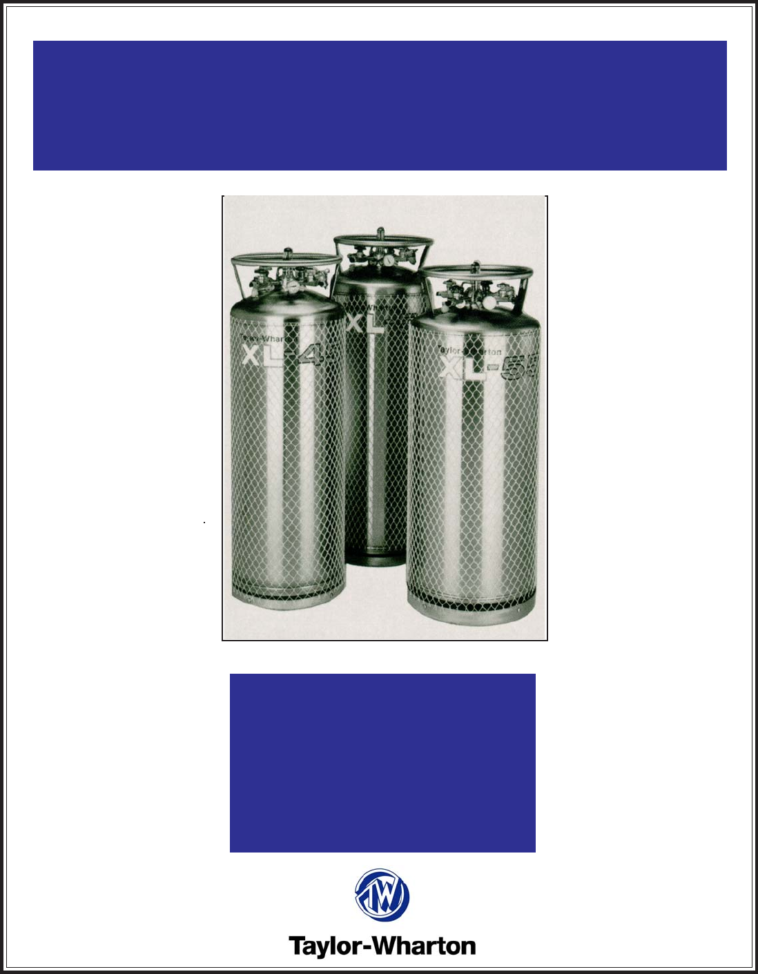
SPECIFICATIONS Dimensions Diameter XL-45 XL-50 XL-55 20 in. (508 mm) 20 in. (508 mm) 20 in. (508 mm) Height Weight Empty (Nominal) 61 ½ in. (1562 mm) 64 5/8 in. (1641 mm) 69 7/8 in. (1764 mm) 255 lb. (116 kg) 270 lb. (122 kg) 270 lb. (122 kg) Capacity, Gross Capacity, Usable Liquid Weight on Contents Max. 180 liters 169 liters 193 liters 181 liters 210 liters 200 liters 388 lb. (176 kg) 416 lb. (189 kg) 454 lb. (206 kg) 273 lb. (124 kg) 471 lb. (214 kg) 293 lb. (133 kg) 505 lb.
Handling the Container The XL Series containers are very rugged liquid cylinders. All cryogenic liquid cylinders have an inner container and an outer container with an insulated vacuum space between them. Any abuse (dents, dropping, tip-over, etc.) can affect the integrity of the containers insulation system. When fully loaded, the XL-55 in argon service will contain 551 lb. (250 kg) of product. While moving a full container, you may be handling 821 lb. (372 kg) and you should treat the load accordingly.
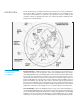
OPERATION XL-45/50/55 Component Locations The XL-45 will store up to 169 liters of product, the XL-50 up to 181 liters and 200 liters for the XL-55. All three cylinders can deliver either liquid or gas. The following component and circuit descriptions are pertinent to the operation of all the containers and should be read before attempting operation. The components may be identified on the Component Location Illustration.
inner container is vaporized in a heat exchanger which is inside the outer casing. The expanding gas is fed into the upper section of the container to build pressure. The resulting pressure will drive either the liquid or gas delivery system. Pressure Building is not normally required unless container pressure drops below the gas output pressure desired. If, for example, the container pressure gauge reads 75 psig (5 bar/517 kPa), and your gas pressure requirement is 100 psig (6.
The VENT Valve – This valve controls a line into the head space of the container. It is used during the fill process. The VENT valve acts as a fill point during a pump transfer, or to vent the head space area while liquid is filling the inner container during a pressure transfer fill through the LIQUID valve. The Pressure Gauge – The pressure gauge displays the internal container pressure in pounds-per-square-inch or in kilo Pascals.
Increasing Gas Supply Capacity – Two or more liquid containers may be manifolded together. Accessory manifolds are available for use in creating a higher capacity gas supply system. The XL-45/50/55 can supply gas at flow rates 1 up to 350 cfh @ NTP (9.2 cu.m/h @ STP) using only its internal vaporizer. At low flow rates, the gas supplied will be at near ambient temperature. As the flow demand is increased, the gas will become proportionately colder.
Determine Proper Fill Weight 1. Visually inspect the container. Do not attempt to fill containers with broken or missing components. NOTE: The weight calculation includes the weight of residual liquid and is applicable to both Pressure Transfer and Pump Transfer filling methods. 2. Move the container to a filling station scale and weight it both with and without the fill hose attached to determine the weight of the fill line assembly. The difference is the fill line weight. 3.
2. During the fill, monitor the container pressure and maintain a pressure of 10-15 psig (0.7-1 bar/69-103 kPa) by throtting the VENT valve. 3. When the full weight is reached, close both the LIQUID and VENT valves. 4. Close the liquid supply valve and open the dump valve on the fill line assembly. 5. Disconnect the fill line from the container and remove the container from the scale.
Fill Hose Kits Fill kits are available with different combinations of hose length and fittings for a specific gas service. The following chart identifies the available transfer hoses and fill tee assemblies. TRANSFER HOSE CHART Description Cylinder (Service/Hose Length) Connections(s) End Fittings Part Number Inert (N2,Ar) Service 4 ft. (1.2 m) Stainless Steel 6 ft. (1.8 m) Stainless Steel 6 ft. (1.8 m) Stainless Steel CGA 295 to 3/8 in. NPT CGA 295 to 3/8 in. NPT CGA 580 to 3/8 in.
Service CGA Connection Part Number Inert (N2, Ar) CGA 295 GL50-8C60 Read the Safety Precautions in the front of this manual before attempting any repairs on these containers. Also follow these additional safety guidelines while performing container maintenance. MAINTENANCE PROCEDURES Never work on a pressurized container. Open the vent valve as a standard practice during maintenance to guard against pressure build-up from residual liquid. Use only repair parts cleaned for oxygen service.
CAUTION: When changing gas service, install the proper fittings – DO NOT use adapters. The following procedures address the physical changes to the container only. For detailed procedures on the decontamination of the container itself, refer to CGA pamphlet C-10 “Changes of Service for Cylinders Including Procedures for Inspection and Contaminant Removal.” GAS SERVICE CHANGE KITS Kit Part No.
Regulator Removal or Replacement Procedure 1. Close manual Pressure Building Valve. 2. Vent the container to atmospheric pressure. 3. Loosen and remove both the tube connections on the pressure building and economizer output sides of the regulator. 4. Remove the regulator from the container by unscrewing the valve body and elbow from the output of the Pressure Building Valve. 5. Repair the regulator and readjust its setpoint using the bench test setup. 6.
CHECKING CONTAINER PERFORMANCE Cryogenic containers are two container, one within the other. The space between the containers acts as a highly efficient thermal barrier including high technology insulation, a vacuum, and a vacuum maintenance system. Each serves a very important part in the useful life of the container. The high technology insulation is very effective in preventing radiated heat from entering the inner container.
WARNING: Cold surfaces should never be handled with bare skin. Use gloves and other protective clothing when performing this procedure. Wharton Customer Service at (334)443-8680 for disposition. FULL VIEW CONTENTS GAUGE MAINTENANCE The content of these containers is measured with the Full View Contents Gauge. The device consists of the gauge assembly beneath a clear plastic protective cover.
NOTE: The yellow band will move approximately ¼ in. (6.4 mm) to each 10 turns of the rod. NOTE: Make sure that the Gauge Assembly is not bent or out of line before reinserting that gauge into the container. Calibration For XL-45, XL-50, XL-55 Contents Gauge Installation Before installing a new or repaired gauge, inspect the gasket seals. If any damage is apparent, replace the gasket. (See following page for illustration.) 1.
again. CAUTION: When installing the gauge assembly, care must be taken to ensure that the float rod is inserted through the “guide ring” located on the liquid withdrawal line inside the container. If the gauge does not engage this ring, the contents indication will be inaccurate, or the gauge may be damaged in use. Contents Gauge Insertion 6.
HAND VALVE REPAIR Hand valve are an integral part of the container, and the valve bodies rarely need replacement. However, the handwheel and internal parts of the valves are renewable. The illustration below are exploded views of the valves replaceable parts used on TaylorWharton liquid containers. Valve Repair Kit Fits: 3/8 in. or 1/2 in. Rego Globe or 3/8 in. Sherwood valves. KIT PARTS - KIT P/N 1750-9C35 Item No.
residue and foreign particles. Valve Replacement Instructions 1. Partially thread Seat Assembly (12) (seat disc first) into large end of Bushing (13) leaving a tang of nipple assembly exposed about 1/8 in. beyond top of Bushing. 2. Insert Seat Assembly (seat disc first) with attached Bushing, into valve body until properly seated. 3. Place Stem Gasket (10) carefully over Stem (11) convex side facing downward. 4.
SHOCK MOUNT FOOT RING Item No. 1 2 3 4 5 Description Part No. (XL-55 Only) Qty. Rubber Shock Ring Foot Ring Hex Nut Washer Carriage Bolt XL50-4C18 XL50-4C19 6310-0135 6430-0125 6620-0401 (GL55-4C21) (GL55-4C19) 1 1 4 4 4 Replacement of Shock Mount Foot Ring 1. Empty or transfer all contents of tank. Vent to atmospheric pressure. 2. Gently lay the container on its side and unbolt the four (4) carriage bolts that attach the foot ring and rubber shock ring to the tank.
TROUBLESHOOTING then inspect your work. The following chart is provided to give you some guidance in determining the probable cause and suggested corrective action for some problems that may occur with cryogenic liquid containers. This chart is specifically tailored to your XL-45, XL-50, or XL-55. TROUBLESHOOTING CHART Symptom Possible Cause Corrective Action Consistently low operating pressure. 1. Relief valve open at low 1. Remove and replace relief pressure. valve. 2. Economizer side of 2.
TROUBLESHOOTING CHART Symptom Possible Cause Corrective Action Container is cold and 1. Vacuum loss. Check NER. 1. Consult with Taylor-Wharton may have ice or frost for course of action. Do not on outer casing. Will attempt to put additional not hold liquid overliquid in container. night. Relief valve is 2. Defective P.B./Economizer 2. Look for P.B. coil pattern in venting gas. regulator. ice. Close P.B. valve. Replace or reset regulator. Ice formation on bottom of container when P.B. valve is closed.
REPLACEMENT PARTS This replacement part list include a recommended inventory quantity which allows you to order part on a timely basis to keep all your XL-45/50/55 containers in service. When placing orders, please use the nomenclature and part numbers in this section and send written orders to: Taylor-Wharton Fax: 1-334-443-2209 4075 Hamilton Blvd.
Index No. 1. * 2. 3. 4. 5. 5a. 6. 7. 8. 9. 10. 11. 12. 14. Description Dual Regulator, Pressure Building/Economizer 125 psig (8.6 bar/862 kPa) Gasket, Glass Filled Teflon, Contents Gauge Contents Gauge Assembly (Includes Gauge and Spring) * Float Rod (45/50) (55) Contents Gauge Cover, Protective Clear Snap-on indicator, Nitrogen Snap-on indicator, Oxygen Snap-on indicator, Argon Screw, Brass, 1/4 in. - 20 UNC x 5/8 in. Washer, Lock, 1/4 in.