Models 904/906 Taylor Express Oven Operating Instructions 050771- M 5/98
Complete this page for quick reference when service is required: Taylor Distributor: Address: Phone: Service: Parts: Date of Installation: Information found on data plate: Model Number: Serial Number: Electrical Specs: Voltage Cycle Phase Maximum Fuse Size: Amps Minimum Wire Ampacity: Amps Part Number: E May, 1998 Taylor All rights reserved. 050771--M The word Taylor and the Crown design are registered trademarks in the United States of America and certain other countries.
Table of Contents ______________________________________________________________________________ Section 1 To the Installer . . . . . . . . . . . . . . . . . . . . . . . . . . . . . . . . . . . . . . . . . . . . Installation . . . . . . . . . . . . . . . . . . . . . . . . . . . . . . . . . . . . . . . . . . . . . . . . . . . . . . . . . . . Air Clearance . . . . . . . . . . . . . . . . . . . . . . . . . . . . . . . . . . . . . . . . . . . . . . . . . . . . . . . . . Electrical Connections . . . . . . . . .
Notes: Models 904/906 Table of Contents
Section 1 To the Installer Installation This unit must be installed with the four 4” metal legs mounted to the base of the unit. These legs are provided with the oven. Remove the legs from the packaging found in the oven cavity, and cap them with the rubber boots (also found in the oven cavity). Mount the legs into the four holes on the bottom of the unit. For proper balancing, level the unit left to right and front to back by adjusting the legs. THESE OVENS ARE NOT FOR HOUSEHOLD USE.
Section 2 To the Operator The oven you have purchased has been carefully engineered and manufactured to give you dependable operation. This oven is designed to reconstitute and/or cook foods. The Model 904 yields two trays of product, while the Model 906 yields four trays of product. The Taylor Models 904 and 906, when properly operated and cared for, will produce a consistent quality product. Like all mechanical products, this machine will require cleaning and maintenance.
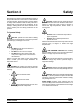
Section 3 Safety We at Taylor are deeply concerned about the safety of the operator when he or she comes in contact with the oven and its parts. Taylor has gone to extreme efforts to design and manufacture built-in safety features to protect both you and the service technician. As an example, warning labels have been attached to the oven to further point out safety precautions to the operator. DO NOT operate the oven unless all service panels and access doors are restrained with screws.
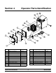
Section 4 Item Description Operator Parts Identification Part No. Item Description Part No. 1 Handle A.-Oven Door X85203 13 Tray-Wire Cooking-8-1/2 Dia. 085052 2 Panel A.-Outer Door X85219 14 Tray-Drip-Oven 085115 3 Panel-Divider Door 085216 15 Mitt-Oven 13” Lg. 085155 4 Insulation-Ceramic Door 085100 16 Carousel-2 Tier 085051 5 Panel A.
Section 5 Important: To the Operator Power Switch Temperature Dial When placed in the “ON” position, the indicator will light, showing that the oven is operable. Turning the temperature dial clockwise allows the operator to choose the desired cooking temperature. Figure 1 Figure 3 Heater Light Timer Dial A heater light is located on the front of the oven. When the light is on, it indicates that the oven is heating.
Door Interlock Switch When the door is open, the blower motor, carousel and heater are not operable. Step 2 Place the door on a flat surface. Remove the four retaining screws from the door cover. Remove the door cover and gasket. Door Gasket For maximum cooking efficiency, replace the door gasket when it is worn. Replacement procedures should be performed as follows: Step 3 Install the new gasket inside the outer ring of the door. Step 1 Remove the door from the oven by lifting if off the hinges.
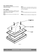
Section 6 Operating Procedures Set-Up Make sure the power switch is in the “OFF” position. If the plenum is in place, proceed to Step 2. Step 1 Install the plenum by sliding it into the oven cavity with the large hole on top. Once the plenum is flush with the porcelain cavity, install the interlock pin by pushing it into the hole at the top of the plenum. Rotate the pin until it is snug. Figure 7 Step 3 Install the door on the hinges and turn the handle to latch the door.
Step 6 When the timer bell rings, remove the product from the oven. Step 6 Clean the wire cooking trays, drip trays, carousel and perforated cavity by soaking them in a strong detergent solution. Step 7 Spray the inside of the oven cavity with a commercial grade oven cleaning solution. CAUTION: To prevent burn injuries, use proper care when loading and unloading trays. Cleaning Procedures The Taylor Express Oven was designed to cook and/or reconstitute food.
Step 11 Re-install the oven door. Step 12 Clean the outside of the oven with a stainless steel cleaner, or sponge it clean with hot, soapy water.
Section 7 Troubleshooting Guide PROBLEM 1. The unit will not operate. 2. The unit is on, but the blower, carousel and heaters will not operate. 3. The unit is on, but will not heat. 4. The unit is on, but the carousel does not turn. 5. The unit is on, but the blower motor does not operate. Troubleshooting Guide PROBABLE CAUSE REMEDY PAGE REF. a. The power switch is in the “OFF” position. a. Place the power switch in the “ON” position. 5 b. The unit is unplugged. b.
PROBLEM 6. The unit takes too long to heat or cook. PROBABLE CAUSE REMEDY PAGE REF. a. Insufficient voltage. a. Contact service technician. b. Incorrect voltage supply or the outlet is not on a dedicated circuit. b. Place the unit on a dedicated circuit with the correct voltage. c. The blower motor is faulty. c. Contact a service technician to replace the blower. d. The temperature dial is not set d. Adjust the temperature dial to properly. the desired setting. e. The heater element is damaged.
Parts List 12 085174 085167 085173 085172 001251 HANDLE--OVEN DOOR PLATE--HANDLE MOUNTING RING--RETAINING SCREW--10--31 X 1/2 X85176 +HANDLE A.--OVEN DOOR *904--906* BUSHING--HANDLE 085178 X85057 +GASKET--DOOR--OVEN DOOR A.--OVEN *904--906* 085213 X85194 DOOR A.--OVEN *904--906* WASHER--.380X.625X,094 NYLON 085119-- DIAGRAM--WIRING *904* 120--60--1 X85219 048200 DEFLECTOR--AIR X85195 085112 DECAL--DEC--OVEN--TEO--4 PANEL A.
+ Available Separately Models 904/906 13 Parts List 085032-085217 085215 X85070 085207 085107 036397 HEATER--TUBULAR--OUTER HINGE--LIFT OFF *904--906* HINGE--LIFT OFF *904--906* KEY A.--INTERLOCK LATCH--DOOR HANDLE *904--906* LATCH--DOOR HANDLE *904--906* LEG--4”--3/8--16 STUD X85000 X85046 X85086 X85054 085056 085208 085209 X85035 X85064 085090 085013 085111-048153 085012 085113 085081-- PANEL A.--FRONT *904--906* PANEL A.--SIDE LEFT *904--906* PANEL A.--SIDE RIGHT *904--906* PANEL A.
+ Available Separately Parts List 14 Models 904/906 085087 +KNOB--THERMOSTAT 085052 TRAY--WIRE COOKING--8--1/2 DIA 085171 085163 PIN--SHELF OVEN TRAY--WIRE COOLING 9 3/4 X 9 3/4 OPTIONAL PARTS 085115 085088 TRAY--DRIP--OVEN +KNOB--TIMER--OVEN 085080 085073 THERMOSTAT--150F--500F TIMER--MECHANICAL--30 MINUTES 085083 PART NUMBER SWITCH--TEMP. OPEN 525 DEG. F DESCRIPTION 1 4 2 2 1 1 1 1 1 904 QTY. 1 4 4 2 1 1 1 1 1 906 QTY.
Model 904 085119-18
Model 906 085119-22
Model 906 085119-24