Model 161 Soft Serve Freezer Operating Instructions 055155-- M 10/02/01
Complete this page for quick reference when service is required: Taylor Distributor: Address: Phone: Service: Parts: Date of Installation: Information found on the data label: Model Number: Serial Number: Electrical Specs: Voltage Cycle Phase Maximum Fuse Size: A Minimum Wire Ampacity: A E October, 2001 Taylor All rights reserved. 055155--M The word Taylor and the Crown design are registered trademarks in the United States of America and certain other countries. Taylor Company 750 N.
Table of Contents Section 1 To the Installer . . . . . . . . . . . . . . . . . . . . . . . . . . . . . . . . . . . . . . . . . . . . Air Cooled Units . . . . . . . . . . . . . . . . . . . . . . . . . . . . . . . . . . . . . . . . . . . . . . . . . . . . . . . Electrical Hook-Up Installation for 60 Cycle, 1 Phase, Supplied With Cord and Plug . . . . . . . . . . . . . . . . . . . . . . . . . . . . . . . . . . . . . . . . . . . Electrical Connections for Models Without Cord and Plug Supplied . . . . . . . . .
Notes: Model 161 Table of Contents
Section 1 To the Installer Electrical Connections This machine is designed for indoor use only. (Models Without Cord and Plug Supplied) DO NOT install the machine in an area where a water jet could be used. Failure to follow this instruction may result in serious electrical shock. Each freezer requires one power supply for each data label. Check the data label on the freezer for fuse, circuit ampacity and electrical specifications.
Section 2 To the Operator The Model 161 soft serve freezer has been carefully engineered and manufactured to give you dependable operation. Compressor Warranty Disclaimer This unit, when properly operated and cared for, will produce a consistent quality product. Like all mechanical products, it will require cleaning and maintenance. A minimum amount of care and attention is necessary if the operating procedures outlined in this manual are followed closely.
Section 3 Safety We at Taylor Company are concerned about the safety of the operator when he or she comes in contact with the freezer and its parts. Taylor has gone to extreme efforts to design and manufacture built-in safety features to protect both you and the service technician. As an example, warning labels have been attached to the freezer to further point out safety precautions to the operator. IMPORTANT -- Failure to adhere to the following safety precautions may result in severe personal injury.
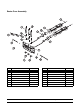
Section 4 Operator Parts Identification Model 161 ITEM DESCRIPTION PART NO. ITEM DESCRIPTION PART NO. 1 PANEL-REAR *161* 055129 9 PANEL A.-SIDE LEFT *161* X55122 2 PANEL-SIDE-RIGHT *161* 055130 10 GASKET-HOPPER COVER 037042 3 LEG-4” 3/8-16 STUD 036397 11 KNOB-MIX COVER 025429 4 CAP-RUBBER 037268 12 COVER A.-HOPPER X37963-SER 5 SHIELD-SPLASH 022765 13 PANEL A.
Beater Door Assembly ITEM DESCRIPTION PART NO. ITEM DESCRIPTION PART NO. 1 DRAW VALVE 024763 9 DESIGN CAP 014218 2 O--RING 7/8 OD X .103 W 014402 10 PIVOT PIN A.--LONG X38538 3 SEAL--VALVE 030930 11 GUIDE BEARING 014496 4 DOOR A.--3 SPOUT X30753--SER 12 CENTER DRAW VALVE 031164 5 PIVOT PIN A.--SHORT X38539 13 O--RING 2--3/4 OD X .139 W 019998 6 O--RING 5/16 OD X .
Accessories ITEM DESCRIPTION PART NO. 1 PAIL-6·QT. 023348 2 BRUSH-REAR BRG 1” D X 2” LG 013071 3 BRUSH-DOUBLE·ENDED 013072 4 BRUSH-DRAW·VALVE·1” OD X 2” X 17” 013073 ITEM DESCRIPTION PART NO. 5 BRUSH-MIX·PUMP·BODY-3”X7” WHITE 023316 6 LUBRICANT-TAYLOR·4·OZ. 047518 7 KIT·A.
Section 5 ITEM 1 2 3 4 5 6 7 Important: To the Operator The following chart identifies the symbol definitions used on the operator switches. DESCRIPTION POWER SWITCH MIX REFRIGERATION KEY STANDBY KEY WASH KEY AUTO KEY INDICATOR LIGHT “MIX LOW” RESET BUTTON = OFF = ON = MIX = STANDBY Symbol Definitions = WASH To better communicate in the International arena, the words on many of our operator switches and keys have symbols to indicate their functions.
Softecht Control Machines WASH Key Note: If your machine is not equipped with Softecht controls, please use the instructions on page 10. When the WASH key is pressed, the light comes on. This indicates beater motor operation. The STANDBY or AUTO modes must be cancelled first to activate the WASH mode. Power Switch AUTO Key When placed in the ON position, the power switch allows Softecht control panel operation. When the AUTO key is pressed, the light comes on.
If the beater motor is turning properly, press the WASH key to cancel the cycle. Press the AUTO key on both sides of the unit to resume normal operation. If the freezer shuts down again, contact a service technician. Air Tube The air tube serves two purposes. One end of the tube has an orifice (hole) and the other end does not. 1. After priming the machine, place the orifice end of the air tube into the mix inlet hole.
Non--Softecht Control Machines Note: If your machine is equipped with the Softecht controls, please use the instructions on page 7. Push-Button Switch If an overload condition occurs, the freezer will automatically stop operating. To properly reset the freezer, place the toggle switch in the OFF position. Wait two or three minutes; then press the push-button switch. Place the power switch in the WASH position and observe the freezer’s performance; place the power switch in the AUTO position.
Section 6 Operating Procedures Assembly The Model 161 is a soft serve counter model with a three spout door. Two individual flavors are available from the end spouts, and an equal combination of both is dispensed through the center spout to create a twist effect. It has a 1.5 quart (1.4 liter) capacity freezing cylinder. The mix flows by gravity from the hopper to the freezing cylinder through an air tube. Note: When lubricating parts, use an approved food grade lubricant (example: Taylor Lube).
Step 3 Place the large o-rings into the grooves on the back of the machine door and lubricate. Figure 8 Note: The freezer door is in the correct position when the door spouts are on the bottom. Step 6 Slide the two o-rings into the grooves on the draw valves and lubricate. Figure 6 Step 4 Slide the front bearings over the baffle rods so the flanged edge is against the door. Place the white plastic guide bearings on the end of the baffle rods.
Step 8 Lubricate the inside of the freezer door spouts from the bottom. Insert the draw valves into the freezer door from the bottom until the slot in the draw valves comes into view. Step 10 Slide the tip of the draw handle into the slot of the draw valve, starting from the right. Slide the short pivot pin through the far right draw handle. Slide the long pivot pin through the far left and middle draw handles. Figure 13 Figure 11 Step 11 Snap the design caps over the bottom of the freezer door spouts.
Sanitizing Step 1 Prepare one gallon (3.8 liters) of an approved 100 PPM sanitizing solution (example: Kay-5r). USE WARM WATER AND FOLLOW THE MANUFACTURER’S SPECIFICATIONS. Step 2 Pour the sanitizing solution into the hopper and allow it to flow into the freezing cylinder. Figure 17 Step 4 Place the power switch in the ON position. Figure 15 Step 3 While the solution is flowing into the freezing cylinder, brush-clean the mix hopper, mix level float, mix inlet hole, and air tube.
Step 5 Press the WASH key. This will cause the sanitizing solution in the freezing cylinder to be agitated. Allow it to agitate for five minutes. Figure 22 Repeat Steps 1 through 7 for the second freezing cylinder. Figure 20 Priming Note: Non--Softecht machines: Place the power switch in the WASH position. This will cause the sanitizing solution in the freezing cylinder to be agitated. Allow it to agitate for five minutes. Prime the machine as close as possible to the time of first product draw.
Step 3 Press the AUTO key. When the unit cycles off, the product will be ready to serve. Step 4 Momentarily raise the draw switch to activate the refrigeration cycle. Step 5 Place the mix hopper cover in position. Repeat Steps 1 through 5 for the second freezing cylinder. Step 6 Install the front drip tray and splash shield under the freezer door. Figure 24 Note: Non--Softecht machines: Place the power switch in the AUTO position. When the unit cycles off, the product will be ready to serve.
Draining Product From the Freezing Cylinder Step 3 Drain all the rinse water from the freezing cylinder. When the rinse water stops flowing from the door spout, close the draw valves and press the WASH key to cancel. Step 1 Press the AUTO key to cancel operation. Press the MIX REF key to cancel hopper refrigeration. These operations should be cancelled as far ahead of cleaning time as possible. This will allow frozen product to soften for easier cleaning.
Disassembly Note: To remove the o-rings, use a single service towel to grasp the o-ring. Apply pressure in an upward direction until the o-ring pops out of its groove. With the other hand, push the top of the o-ring forward, and it will roll out of the groove and can be easily removed. If there is more than one o-ring to be removed, always remove the rear o-ring first. This will allow the o-ring to slide over the forward rings without falling into the open grooves.
Section 7 Important: Operator Checklist During Cleaning and Sanitizing j 7. Properly prepare the cleaning and sanitizing solutions. Read and follow label directions carefully. Too strong of a solution may damage the parts and too weak of a solution will not do an adequate job of cleaning or sanitizing. ALWAYS FOLLOW LOCAL HEALTH CODES. j 8. The temperature of the mix in the mix hopper and walk-in cooler should be below 40_F. (4.4_C.).
Winter Storage j 6. If your machine is equipped with an auxiliary refrigeration system, check the auxiliary condenser for accumulation of dirt and lint. A dirty condenser will reduce the refrigeration capacity of the mix hopper. Condensers must be cleaned monthly with a soft brush. Never use screwdrivers or other metal probes to clean between the fins. Failure to comply may result in electrocution.
Section 8 PROBLEM 1. No product being dispensed. 2. The machine will not operate in the AUTO mode. 3. The product is too stiff. Model 161 Troubleshooting Guide PROBABLE CAUSE REMEDY PAGE REF. a. The power switch is in the OFF position. a. Place the power switch in the AUTO position. 14 b. The mix level is inadequate in the mix hopper. b. Fill the mix hopper with mix. 15 c. The beater motor overloaded. c. Reset the freezer. 10 d. The unit is unplugged at the wall receptacle. d.
PROBLEM 4. The product is too soft. 5. The freezing cylinder walls are scored. 6. Excessive leakage in rear drip pan. 7. The draw valve is leaking. 8. Product is not feeding into the freezing cylinder. Troubleshooting Guide PROBABLE CAUSE REMEDY PAGE REF. a. The control is set too warm. a. Contact service technician. 10 b. The air tube is not installed. b. Install the air tube in the mix inlet hole at the bottom of the mix hopper. 15 c. Out-drawing the freezer’s capacity. c. Two 4 oz. (113.
PROBLEM 9. The unit goes out on overload excessively. 10. Mix from one freezing cylinder bleeds over to the second cylinder. Model 161 PROBABLE CAUSE REMEDY PAGE REF. a. There are too many appliances plugged into the circuit. a. A separate 20A circuit is needed for the freezer to operate properly. --- b. An extension cord has been placed between the power cord and the wall receptacle. b. If the extension cord is used, it must match the power cord in size of circuit ampacity. --- a.
Section 9 PART DESCRIPTION Parts Replacement Schedule EVERY 3 MONTHS EVERY 6 MONTHS ANNUALLY QTY.
Model 161 25 013071 032445 014218 019481 051958-27 BRUSH-REAR BRG 1IN.DX2IN.LGX14 CABLE-RIBBON-PWR/RELAY-60 IN CAP-DESIGN-1.010”ID-6 POINT COLLAR-HOLDING COMPRESSOR RS80C1E-CAV-224 055140 055248-27 X37963 CONDENSER-AC-12LX16HX2.5-3 ROW CONTACTOR-230VAC 1PH 50/60HZ COVER A.
+ Available Separately Parts List 26 Model 161 X31167 KIT A.-TUNE UP*162-168* 019998 016272 014402 030930 O-RING-2-3/4 OD X .139W O-RING-5/16 OD X .070W O-RING-7/8 OD X .103W SEAL-VALVE 021278 X55118 HOOD A. *161* SOLDERED O-RING-13/16 OD X .139W 025770 GEAR A.*REDUCER 4 TO 1 014218 042703 FILTER-AIR 13.5X17.75X7/16 CAP-DESIGN-1.
+ Available Separately Model 161 27 Parts List 037268 +CAP-RUBBER X55203 X55122 055513 055129 055130 055508 055512 X30922 PANEL A.-FRONT *161* PANEL A.-SIDE LEFT *161* PANEL-LOWER FRONT *161* GENII PANEL-REAR *161* PANEL-SIDE-RIGHT *161* PANEL-SKIRT-AIR *161* PLATE-DEC *161* GENII PROBE A.-MIX *SQUARE* X31602 038061-BLK 041498 041162 PROBE A.-THERMISTOR PROBE-THERMISTOR-BARREL-2% TOL PULLEY-5.
+ Available Separately Parts List 28 Model 161 X55629 SHELL A.
+ Available Separately Model 161 29 Parts List 023606 CAPACITOR-RUN- 20UF/370V VIDEO-TRAIN FILM-SS-TAYLORMATE CAPACITOR-START- 64-77UF/250V 037665-PAL 026657 055097-34 051960 MOTOR-1/2 HP 1 PH 50 HZ 230V 051957-40 051958-40 COMPRESSOR RS80C1E-CAZ-224 CAPACITOR-START- 64-77UF/250V 055376-40S RELAY-START-COMPRESSOR 024156 DIAGRAM-WIRING *161* PART NUMBER BLOCK-TERMINAL-7 POLE GREEN 50Hz DESCRIPTION 1 2 2 1 1 1 1 1 1 QTY. 000 103 212 103 103 103 512 000 103 WARR.
Model 161 055376--27S Rev.
Model 161 055376--40S Rev.