Model H63 Shake Freezer Original Operating Instructions 048887-- M 5/09/02 (Original Publication) (Updated 11/14/11)
Complete this page for quick reference when service is required: Taylor Distributor: Address: Phone: Service: Parts: Date of Installation: Information found on the data label: Model Number: Serial Number: Electrical Specs: Voltage Cycle Phase Maximum Fuse Size: A Minimum Wire Ampacity: A E May, 2002 Taylor All rights reserved. 048887--M The word Taylor and the Crown design are registered trademarks in the United States of America and certain other countries. Taylor Company 750 N. Blackhawk Blvd.
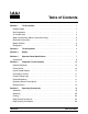
Table of Contents To the Installer . . . . . . . . . . . . . . . . . . . . . . . . . . . . . . . . . . . . . . . . . . . . 1 Installer Safety . . . . . . . . . . . . . . . . . . . . . . . . . . . . . . . . . . . . . . . . . . . . . . . . . . . . . . . . 1 Site Preparation . . . . . . . . . . . . . . . . . . . . . . . . . . . . . . . . . . . . . . . . . . . . . . . . . . . . . . . 1 Air Cooled Units . . . . . . . . . . . . . . . . . . . . . . . . . . . . . . . . . . . . . . . . . . . . . . . . . . . .
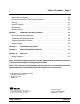
Table of Contents -- Page 2 Manual Brush Cleaning . . . . . . . . . . . . . . . . . . . . . . . . . . . . . . . . . . . . . . . . . . . . . . . . 26 Draining Product From The Freezing Cylinder . . . . . . . . . . . . . . . . . . . . . . . . . . . . 26 Rinsing . . . . . . . . . . . . . . . . . . . . . . . . . . . . . . . . . . . . . . . . . . . . . . . . . . . . . . . . . . . . . . 27 Hopper Cleaning . . . . . . . . . . . . . . . . . . . . . . . . . . . . . . . . . . . . . . . . . . . . . . . . . . .
Section 1 To the Installer Site Preparation The following are general installation instructions. For complete installation details, please see the check out card. Installer Safety Review the area the unit is to be installed in before uncrating the unit, making sure that all possible hazards the user or equipment may come into have been addressed. In all areas of the world, equipment should be installed in accordance with existing local codes.
Air Cooled Units Each freezer requires one power supply. Check the data label on the freezer for fuse, circuit ampacity and electrical specifications. Refer to the wiring diagram provided inside of the control box, for proper power connections. DO NOT obstruct air intake and discharge openings: Air cooled units require a minimum of 6” (152 mm) of clearance around all sides of the freezer and 7--1/2” (191 mm) on the bottom to allow for adequate air flow across the condenser.
Beater Rotation Refrigerant liquid sprayed onto the skin may cause serious damage to tissue. Keep eyes and skin protected. If refrigerant burns should occur, flush immediately with cold water. If burns are severe, apply ice packs and contact a physician immediately. Beater rotation must be clockwise as viewed looking into the freezing cylinder. Note: The following procedures must be performed by an authorized Taylor service technician.
Section 2 To the Operator The Model H63 shake freezer has been carefully engineered and manufactured to give you dependable operation. This unit, when properly operated and cared for, will produce a consistent, quality product. Like all mechanical products, it will require cleaning and maintenance. A minimum amount of care is necessary if the operating procedures outlined in this manual are followed closely.
Section 3 Safety We at Taylor Company are concerned about the safety of the operator when he or she comes in contact with the freezer and its parts. Taylor has gone to extreme efforts to design and manufacture built--in safety features to protect both you and the service technician. As an example, warning labels have been attached to the freezer to further point out safety precautions to the operator.
DO NOT draw product or attempt to disassemble the unit during the HEAT cycle. The product is hot and under extreme pressure. DO NOT allow untrained personnel to operate this machine. S DO NOT operate the freezer unless all service panels and access doors are restrained with screws. S DO NOT remove any internal operating parts (examples: freezer door, beater, scraper blades, etc.) unless all control switches are in the OFF position.
Section 4 Operator Parts Identification H63 ITEM DESCRIPTION PART NO. ITEM DESCRIPTION PART NO. 1 COVER A.--HOPPER INS. 053809 13 TUBE A.--FEED--OUTER--HT X34641 2 AGITATOR A. *HT*20 QT X44797 14 O--RING--.291 ID X .080W 018550 3 PANEL A.--SIDE LEFT X48285 15 TUBE A.--FEED--SC--INNER X32824--5 4 STUD--NOSE CONE 011390 16 ADAPTOR A.
H63 Door and Beater Assemblies ITEM DESCRIPTION PART NO. ITEM 1 SEAL--DRIVE SHAFT 032560 9 2 SHAFT--BEATER 035527 3 BEATER A.--7QT--1 PIN 4 DESCRIPTION PART NO. O--RING--.291 ID X .080W 018550 10 DOOR A.--1 SPOUT--METAL X17373 X46233 11 VALVE A.--DRAW X56119 BEARING--FRONT 013116 12 O--RING--1--1/16 OD X .139W 013029 5 GASKET--DOOR 5.177ID 016672 13 NUT--STUD *GENERAL USAGE* 021508 6 BEARING--GUIDE 014496 14 BLADE--SCRAPER--PLASTIC 046237 7 TORQUE A.
Accessories 3 048260 8 1 2 7 4 R LU BE HP 5 6 ITEM 1 DESCRIPTION PART NO. BRUSH-MIX PUMP BODY 3” X 7” WHITE 023316 2 BRUSH-END-DOOR-SPOUT 039719 3 KIT A.-TUNE UP X48404 4 BRUSH-DOUBLE ENDED 013072 ITEM DESCRIPTION PART NO. 5 BRUSH-REAR BRG 1IN.D X 2IN 013071 6 BRUSH-DRAW VALVE 014753 7 LUBRICANT-TAYLOR HI PERF 048232 8 PAIL-MIX 10 QT.
Section 5 Important: To the Operator H63 The following chart identifies the symbol definitions used on the operator switches. Item 1 2 3 4 5 6 Description = ON Power Switch (Toggle) Liquid Crystal Display LCD Indicator -- MIX LOW (PCB A.--LED) LCD Indicator -- MIX OUT (PCB A.
Liquid Crystal Display Reset Mechanism The Liquid Crystal Display (LCD) is located on the front control panel. The LCD is used to show the current mode of operation, and whether or not there is sufficient mix. The reset button is located under the right side panel. The reset mechanism protects the beater motor from an overload condition. If an overload occurs, the reset mechanism will trip.
Once the system has initialized the SAFETY TIMEOUT screen is displayed and the alarm is turned on. MODE: ON MIX: OK HOPPER TEMP: 40.0F BRUSH CLEAN ON: MM/DD SAFETY TIMEOUT ANY KEY ABORTS The next display indicates the freezer is operating in two different modes. The following information is given: The machine is operating in the WASH mode and the mix level in the hopper is low. The temperature of the mix hopper is 40_F (4.4_C), and the machine needs to be brush cleaned on October 31st.
The final phase of the heat treatment cycle is the cooling phase. Now the freezer must cool the mix below 41_F (5_C). If the product fails to cool in two hours, the freezer will lock out. The next display is the screen which will appear after the failure message. To comply with health codes, heat treatment system freezers must complete a heat treatment cycle daily, and must also be brush cleaned every 14 days. Brush cleaning is the normal disassembly and cleaning procedures.
Following are the variable messages which will appear on line 3: 1. POWER SWITCH OFF: Power switch was in the OFF position. 2. MIX OUT PRESENT: There was a mix out condition present. 3. AUTO OR STANDBY OFF: The unit was not in the AUTO or STANDBY mode. 4. NO HEAT CYCLE TRIED: A heat treatment cycle was not attempted in the last 24 hours. (AUTO HEAT TIME was advanced, or a power loss was experienced at the time the cycle was to occur, or a heat cycle failure not due to a thermistor failure.
Clearing Fault Tones 9. To clear the tone for any faults which have been corrected, press the <-- -- arrow key. To see if there is more than one fault, press the MENU/SEL key. When the last fault is displayed, the control will return to the OPERATOR MENU. To return to the main screen, move the cursor to “A” and press the MENU/SEL key again. 10. Listed below are the variable messages which will appear, along with the corrective action: 1. NO FAULT FOUND: There was no fault found in the freezer.
Pressing the <-- -- arrow key or the -- --> arrow key will move the cursor left or right respectively. Pressing the MENU/SEL key while under “ENABLE” will accept the selection and will automatically increase the clock one hour at 2:00 a.m. on the first Sunday in every April. It will decrease one hour at 2:00 a.m. on the last Sunday in every October. Pressing the MENU/SEL key while under “DISABLE” will accept the selection and operate normally.
Screen “G” is HEAT CYCLE DATA. The information from the previous heat treatment cycles can be obtained through this screen. The most recent heat treatment cycle data will be shown first; press the plus key to scroll through the remaining heat cycle displays. If a heat treatment cycle failure should occur, a two character message will appear on the second line of the screen. Press the MENU/SEL key once to return to the OPERATOR MENU. 00:00 00:00 HEAT OVER 00:00 00:00 TEMP AT END 00:00 COOL 00:00 0.
Section 6 Operating Procedures The Model H63 has a one 7 quart (6.6 liter) freezing cylinder. This automatic freezer offers one flavor. We begin our instructions at the point where we enter the store in the morning and find the parts disassembled and laid out to air dry from the previous night’s brush cleaning. These opening procedures will show you how to assemble these parts into the freezer, sanitize them, and prime the freezer with fresh mix in preparation to serve your first shake.
Step 2 Install the beater assembly. First check scraper blades for any nicks or signs of wear. If any nicks are present, replace both blades. If blades are in good condition, install the scraper blade clips on the scraper blades. Place the rear scraper blade over the rear holding pin on the beater. Figure 5 Step 3 Install the torque rotor assembly. Assemble the torque rotor by sliding the two o--rings on the front of the shaft and lubricate them thoroughly to prevent leaking.
Step 4 Install the draw valve. Slide the two o--rings onto the draw valve and lubricate. Figure 10 Figure 8 Lubricate the inside of the door spout, top and bottom, and insert the draw valve into the freezer door from the top. It will be necessary to rotate the draw valve to the right when assembling the door to the freezer. Install the freezer door. Locate the torque rotor in the center hole of the freezer door.
Step 6 Install the rear drip pan. Slide the drip pan into the hole in the front panel. Step 9 Slide the three o--rings into the grooves of the inner air tube. Figure 14 Slide the two o--rings into the grooves of the outer air tube. Figure 12 Step 7 Install the torque arm. Position the torque arm by slipping it up through the slot in the operating arm, and then down into the hole in the torque rotor shaft. Check the torque arm by moving it back and forth to be sure it moves freely and easily.
Sanitizing Step 6 With a pail beneath the dispensing spout, open and close the draw valve six times. Draw off the remaining sanitizing solution. Step 1 Prepare a pail of an approved 100 PPM sanitizing solution (examples: 2--1/2 gal. [9.5 liters] of Kay--5R or 2 gal. [7.6 liters] of Stera--SheenR). USE WARM WATER AND FOLLOW THE MANUFACTURER’S SPECIFICATIONS. Step 2 Pour the sanitizing solution over all the parts in the bottom of the mix hopper and allow it to flow into the freezing cylinder.
When full strength mix is flowing from the dispensing spout, close the draw valve. Step 9 Stand the assembled air tubes in the corner of the mix hopper and place the agitator on the agitator housing. Figure 20 Note: If the agitator stops turning during normal operation, remove the agitator from the agitator housing and brush clean these parts with sanitizing solution. Install the agitator back onto the agitator housing. Be sure your hands are sanitized when performing this step.
Step 3 Press the AUTO key. When the unit cycles off, the product will be ready to serve. Step 1 Remove the hopper cover, assembled air tube, and agitator. Take these parts to the sink for further cleaning and sanitizing. Note: Pressing the <-- -- arrow key will stop the agitator rotation for ten seconds. Figure 24 Step 4 Fill the hopper with fresh mix and place the mix hopper cover in position. Note: Use only FRESH mix when priming the freezer.
CYCLE FAILURE -- FREEZER LOCKED -- PRESS SEL KEY”. The product may not be safe to serve. The freezer will be locked out of the AUTO mode. Discard product and brush clean machine. Step 5 Install the air tube assembly. Lift and turn the inner air tube of the assembled air tubes so the pin rests on top of the outer air tube. This will close the hole in the assembled air tubes, preventing mix in the hopper from entering the freezing cylinder during the heating and standby process.
Draining Product From The Freezing Cylinder Rinse a single service towel in sanitizing solution and wipe down the freezer door and area around the bottom of the freezer door. Replace the front drip tray and splash shield. MAKE SURE YOUR HANDS ARE SANITIZED BEFORE PERFORMING THIS NEXT STEP! Step 3 Lift hopper cover and turn the inner air tube of the assembled air tubes so the pin rests at the bottom of the notch of the outer air tube.
Rinsing Step 4 Press the WASH key and allow the cleaning solution in the freezing cylinder to agitate for five minutes. Step 1 Pour two gallons (7.6 liters) of cool, clean water into the mix hopper. With the brushes provided, scrub the mix hopper, mix level sensing probes, the outside of the agitator housing, and the mix inlet hole. Step 5 Place an empty pail beneath the door spout. Step 6 Open the draw valve on the freezer door and draw off all the solution.
Brush Cleaning Step 3 Remove the o--rings from the inner and outer air tubes. Step 4 Return to the freezer with a small amount of cleaning solution. With the black bristle brush, brush clean the rear shell bearing at the back of the freezing cylinder. Step 1 Prepare a sink with an approved cleaning solution (examples: Kay--5R or Stera--SheenR). USE WARM WATER AND FOLLOW THE MANUFACTURER’S SPECIFICATIONS.
Section 7 Important: Operator Checklist During Cleaning and Sanitizing Regular Maintenance Checks Cleaning and sanitizing schedules are governed by your State or local regulatory agencies and must be followed accordingly. The following check points should be stressed during the cleaning and sanitizing operations. CLEANING AND SANITIZING MUST BE PERFORMED EVERY 14 DAYS. j 1. Rotate the scraper blades to allow both sides of the knife edge to wear evenly.
Winter Storage Disconnect the freezer from the main power source to prevent possible electrical damage. If the place of business is to be closed during the winter months, it is important to protect the freezer by following certain precautions, particularly if the building is subject to freezing conditions. Your local Taylor Distributor can perform this service for you.
Section 8 PROBLEM 1. Soft lock message appears on LCD. Model H63 Troubleshooting Guide PROBABLE CAUSE PAGE REF. REMEDY a. More than 24 hours since the last heat cycle. a. The freezer must go through a heat cycle every 24 hours. The freezer must now be disassembled and brush cleaned or placed in a heat cycle. 14 b. The power switch is in the OFF position. b. The power switch must be in the ON position. The freezer must now be disassembled and brush cleaned or placed in a heat cycle. 14 c.
PROBLEM 2. Hard lock message appears on LCD. 3. No product being dispensed with draw valve open and machine in the AUTO mode. 4. The product is too stiff. Troubleshooting Guide PAGE REF. PROBABLE CAUSE REMEDY a. There has been a thermistor failure (freezing cylinder, hopper, or glycol) during the heat treatment process. a. The freezer must be disassembled and brush cleaned. 13 b. More than 14 days since last brush cleaning. b. The freezer must be disassembled and brush cleaned every 14 days.
PROBLEM 5. The product is too soft. PROBABLE CAUSE PAGE REF. REMEDY a. Improper consistency control adjustment. a. Product, with no syrup blended (vanilla), should be dispensed at 26_ to 28_F. (-3.3_ to -2.2_C.). 11 b. The torque rotor is binding. b. Before installing the torque arm, check to see if the torque rotor can be rotated freely without binding. 19 c. Improper lubrication of torque rotor o-rings. c. Lubricate the o-rings properly. 20 d. Lubrication of torque rotor guide bearing. d.
PROBLEM 9. The freezing cylinder walls are scored. 10. Excessive mix leakage from the dispensing spout. 11. Excessive mix leakage into the rear drip pan. Troubleshooting Guide PROBABLE CAUSE REMEDY PAGE REF. a. The beater assembly is bent. a. Call a service technician to repair or replace beater and to correct cause of insufficient mix in freezing cylinder. b. The front bearing is missing or worn. b. Install or replace front bearing. c. The gear box is out of alignment. c.
PROBLEM 12. No freezer operation after placing unit in the AUTO mode. 13. Liquid Crystal Display is blank after power switch is placed in the ON position. 14. Product not feeding into freezing cylinder. Model H63 PROBABLE CAUSE PAGE REF. REMEDY a. Unit unplugged. a. Plug into wall receptacle. ------ b. Circuit breaker off or blown fuse. b. Turn circuit breaker on or replace fuse. ------ c. Beater motor out on reset. c. Clear the tone and reset freezer. 11 d.
Section 9 PART DESCRIPTION Parts Replacement Schedule EVERY 3 MONTHS EVERY 6 MONTHS ANNUALLY QTY.
Model H63 031324 BEARING-REAR SHELL *NICK.PLATE 37 040322-005 040322-002 040322-003 040322-004 013072 014753 039719 023316 013071 040040-023 BLOCK-TERMINAL-PLUG 10P .2 SIP BLOCK-TERMINAL-PLUG 6P .2 SIP BLOCK-TERMINAL-PLUG 7P .2 SIP BLOCK-TERMINAL-PLUG 8P .2 SIP BRUSH-DOUBLE ENDED-PUMP&FEED TUBE BRUSH-DRAW VALVE 1-1/2”OD X 3” BRUSH-END-DOOR-SPOUT-SS-HT BRUSH-MIX PUMP BODY-3”X7”WHITE BRUSH-REAR BRG 1IN.DX2IN.
+ Available Separately Parts List 38 Model H63 018794 047344 050716 047520- CASTER-SWV 5/8 STEM 4IN WHEEL CLAMP-HOSE 9/16 CRIMP TYPE CHART-FLIP COMPRESSOR AH7513Z-AH245ET 048358 046699 038374 048384- DECAL-DEC-TAYLOR-H63 (OLD) DECAL-MANUAL CLEANING-HT-H60 DECAL-TROUBLESHOOTING DIAGRAM-WIRING *H63* +GASKET-DOOR 5.177ID X 5.938OD 016672 X17373 052284 DECAL-DEC-TAYLOR-H63 (NEW) DOOR A.-PARTIAL-1 SPT *452 046698 DECAL-DAILY CLEANING-HT-SH-H60 X38062-SER 053809 COVER A.-HOPPER INS.
+ Available Separately Model H63 39 Parts List 012235 047988 X47900 X47331- GEAR A.*REDUCER GEAR A.*REDUCER-AGITATOR GUIDE A.-DRIP PAN *H60* HEATER A.-GLYCOL-2500W *H60* 014496 016672 018550 018572 013029 032560 048260-WHT BEARING-GUIDE GASKET-DOOR 5.177ID X 5.938OD O-RING-.291 ID X .080W O-RING-.643 OD X .077W O-RING-1-1/16 OD X .139W SEAL-DRIVE SHAFT TOOL- O-RING REMOVAL 014499 013116 KNOB-ADJUSTMENT X48404 006812 SCREW-8-32 X 3/16 ALLEN SET BEARING-FRONT X41733 KIT A.
+ Available Separately Parts List 40 Model H63 051433 038221 LABEL-WARN COVER LENS-DISPLAY 013631 048232 048887-M LOUVER-SIDE LUBRICANT-TAYLOR HI PERF-4 OZ MAN-OPER *H63* 026980-SP 048380 X48285 PANEL A.-SIDE *H60*LEFT PANEL-SERVICE *H63* X48371 PANEL A.-FRONT *H63* PANEL-REAR W/LOUVERS *5472* 035034 PAN-DRIP 19-1/2 LONG X48286 013163 PANEL A.-SIDE *H60*RIGHT 021508 PAIL-MIX 10 QT.
+ Available Separately 051103 Model H63 41 Parts List 2 X42077 X41348 024278 PROBE A.-MIX LOW-HT PROBE A.-MIX OUT-SQUARE HOLE 1 1 035527 032560 SHAFT-BEATER X46622 013356 046177 SHELL A.
+ Available Separately Parts List 42 Model H63 049178 015478 043527 038981 027219 039252 E-RING 3/16 .335 O.D. PIN-PIVOT PLATE-DRAW SWITCH *452 HT* SCREW-10-32X9/16 DOG PT SET SCREW-4-40 X 5/8 RHM-ZP STEEL SWITCH-LEVER-SPDT-11A-125-250V 044520 048230 024295 047314 X17381 SWITCH-PRESSURE 440 PSI-SOLDER SWITCH-TOGGLE-DPDT*ON-NONE-ON TANK-GLYCOL 1.5QT-PLASTIC TORQUE A. *452-453* 046668 X34641 018572 TRIM-REAR CORNER *H60* TUBE A.-FEED-OUTER-HT +O-RING-.643 OD X .077W +O-RING-.291 ID X .
+ Available Separately Model H63 43 Parts List 047016 046365 VALVE-ACCESS-1/4 MFLX1/4 S-90 VALVE-EXP-AUTO-1/4S X1/4 FPT R50200 048231 HOSE-RUBBER 1/2” X 7/8 SWITCH-PRESSURE 350 PSI 007098 024156 039424 027087 036084 033043 035798 045717 045718 033559 BELT BLOCK-TERMINAL-7 POLE GREEN BLOCK-TERMINAL 3P+ N CAPACITOR-RUN (MAGNETEK) CAPACITOR-RUN (LEESON) CAPACITOR-START (MAGNETEK) CAPACITOR-START (LEESON) PULLEY-AGITATOR DRIVE PULLEY-AGITATOR MOTOR PULLEY-AK 30 x 5/8 (MOTOR) 50 Hz 046686
Model H63 048384--27 Rev.
Model H63 048384--33 Rev.
Model H63 048384--58 Rev.