Model C302 Slush Freezer Original Operating Instructions 059661-M 6/22/04 (Original Publication) (Updated 4/5/11)
Complete this page for quick reference when service is required: Taylor Distributor: Address: Phone: Fax: E-mail: Service: Parts: Date of Installation: Information found on the data label: Model Number: Serial Number: Electrical Specs: Voltage Cycle Phase Maximum Fuse Size: A Minimum Wire Ampacity: A E June, 2004 Taylor All rights reserved. 059661-M The word Taylor and the Crown design are registered trademarks in the United States of America and certain other countries. Taylor Company 750 N.
Table of Contents Section 1 To the Installer . . . . . . . . . . . . . . . . . . . . . . . . . . . . . . . . . . . . . . . . . . . . 1 Section 2 To the Operator . . . . . . . . . . . . . . . . . . . . . . . . . . . . . . . . . . . . . . . . . . . 5 Section 3 Safety . . . . . . . . . . . . . . . . . . . . . . . . . . . . . . . . . . . . . . . . . . . . . . . . . . . . 6 Section 4 Operator Parts Identification . . . . . . . . . . . . . . . . . . . . . . . . . . . . . . . 8 C302 . . . . . . . . . .
Table of Contents - Page 2 Disassembly . . . . . . . . . . . . . . . . . . . . . . . . . . . . . . . . . . . . . . . . . . . . . . . . . . . . . . . . . . 31 Brush Cleaning . . . . . . . . . . . . . . . . . . . . . . . . . . . . . . . . . . . . . . . . . . . . . . . . . . . . . . . 32 Section 7 Important: Operator Checklist . . . . . . . . . . . . . . . . . . . . . . . . . . . . . . 33 During Cleaning and Sanitizing . . . . . . . . . . . . . . . . . . . . . . . . . . . . . . . . . . . . . . . . .
To the Installer Section 1 The following are general installation instructions. For complete installation details, please see the checkout card. This unit has many sharp edges that can cause severe injuries. Installer Safety Site Preparation In all areas of the world, equipment should be installed in accordance with existing local codes. Please contact your local authorities if you have any questions. Review the area where the unit will be installed before uncrating the unit.
Air Cooled Units Water Connections An adequate cold water supply must be provided with a hand shut-off valve. On the back of the unit, a 3/8” (9.5 mm) M.F.L. water connection has been provided for easy hook-up. A flexible line is recommended, if local codes permit. A minimum of 25 psi water pressure is required to avoid having the unit cut out the low water pressure switch. A booster pump must be provided if this pressure is not available. Note: Water lines beyond 200 ft.
Electrical Connections Each freezer requires one power supply. Check the data label on the freezer for branch circuit overcurrent protection or fuse, circuit ampacity and electrical specifications. Refer to the wiring diagram provided inside of the control box, for proper power connections. S In the United States, this equipment is intended to be installed in accordance with the National Electrical Code (NEC), ANSI/NFPA 70-1987.
Initial Freezing Cylinder Cleaning Due to the types of products used in FCB equipment, it is imperative that the freezing cylinder and the inlet tube be thoroughly brush cleaned, rinsed, and sanitized before running any product. Prepare a cleaning solution, using 2 oz. of liquid detergent in 2 gallons of warm water. Using this solution, brush clean the freezing cylinder and the inlet tube. Rinse the freezing cylinder and the inlet tube with clean water.
Section 2 To the Operator The freezer you have purchased has been carefully engineered and manufactured to give you dependable operation. unsorted municipal waste. The user is responsible for returning the product to the appropriate collection facility, as specified by your local code. The Model C302, when properly operated and cared for, will produce a consistent quality product. Like all mechanical products, this machine will require cleaning and scheduled maintenance.
Safety Section 3 We, at Taylor Company, are concerned about the safety of the operator when he or she comes in contact with the freezer and its parts. Taylor has gone to extreme efforts to design and manufacture built-in safety features to protect both you and the service technician. As an example, warning labels have been attached to the freezer to further point out safety precautions to the operator.
This unit must be installed on a level surface to avoid the hazard of tipping. Extreme care should be taken in moving this equipment for any reason. Two or more persons are required to safely move this unit. Failure to comply may result in personnel injury or equipment damage. S DO NOT allow untrained personnel to operate this machine. S DO NOT operate the freezer unless all service panels and access doors are restrained with screws.
Section 4 Operator Parts Identification C302 Figure 2 ITEM DESCRIPTION PART NO. ITEM DESCRIPTION PART NO.
Beater Door Assembly Figure 3 ITEM DESCRIPTION PART NO. ITEM DESCRIPTION PART NO. 1 DOOR A.-SLUSH PRESS. X39572-BLA 1m O-RING-1.129 ODX.989ID 039219 1a CAP-SPOUT-DOOR-FCB-BLK 046191-BLA 1n NUT-SPOUT-DOOR-PRESS. 039323 1b SPRING-COMP.480X.072X3.0 039320 1o 017003 1c VALVE-DRAW-DOOR-PRESS. 039324 O-RING-5-1/4ODX.210W (DOOR) 1d O-RING-9/16 OD X .
Accessories Figure 4 ITEM DESCRIPTION PART NO. ITEM DESCRIPTION PART NO. 1 PAIL-MIX 10 QT 013163 5 BRUSH-DRAW VALVE 1-1/2”OD 014753 2 BRUSH-MIX PUMP BODY-3”X7” 023316 6 KIT A.
Section 5 Important: To the Operator Figure 5 ITEM 1 2 3 4 5 Control Switches DESCRIPTION There are two control switches located at the top left corner of the upper front panel, behind the illuminated display. The left switch controls the two freezing cylinders on the left side of the unit. The right switch controls the two freezing cylinders on the right side of the unit. When placed in the ON position, these control switches allow SLUSHTECH operation.
Pressing the AUTO (- ->) keys for each freezing cylinder will display this screen. Liquid Crystal Displays There are two Liquid Crystal Displays (LCD's) located on the upper front panel behind the illuminated display. The two LCD's display information for the two freezing cylinders located directly beneath them. These pairs of freezing cylinders are each labeled “left” and “right” per LCD. AUTO OK CO2-OK WATER-OK Line 2 indicates the status of the syrup systems in each freezing cylinder.
2. Operator Menu Timeout If the display is left in the operator menu or any of the operator menu selections, except for Current Conditions, the display will return to the system mode screen 60 seconds after the last keypress. The Current Conditions screen will be displayed until manually changed. BEATER OVERLOAD - Beater motor is out on overload. When this fault occurs, the affected side of the machine automatically turns off. The fault clears when the condition is corrected.
6. SYRUP PRESS LOW - When the syrup out indicator displays a lack of syrup, the barrel will enter a HOLD mode. At this time, no refrigeration or product flow from the flow control will be allowed. Only the beater will operate. When the syrup is satisfied the barrel will refill the product tank and then automatically return to the AUTO mode. The fault message and the warning tone will clear. (See “Syrup Out Indicator” on page 17.) FAULT DESCRIPTION L: NO FAULT FOUND R: SYRUP PRESS LOW CLR +++ 7. SEL 10.
Screen C is SET CLOCK. Use the AUTO (- ->) and OFF (<- -) keys to place the cursor under the element to be set (hours, minutes, month, day, or year). Use the PRIME (+++) and BEATER (- - -) keys to increment or decrement the value. Press the MENU (SEL) key to advance to the Daylight Saving Time screen. Repeat the procedure for the right freezing cylinder under each LCD. MANUAL DEFROST RIGHT SIDE NO YES <- - - -> SEL Note: The clock is programmed with military time.
The fourth feature will display the Power Saver Mode, OFF, REST, or STANDBY status. DEFROST TIME RIGHT SUN CYCLE 1 If the Power Saver Mode is OFF, the following screen will be displayed. <- - - ->+ + + POWER SAVER MODE OFF 10:00 --- SEL Press the MENU (SEL) key to return to the OPERATOR MENU. SEL Screen F is CURRENT CONDITIONS. This screen displays the current viscosity and product temperature for each freezing cylinder. An asterisk will indicate which side is refrigerating.
Press the AUTO (- ->) key to move to the next screen. The next screen will indicate when the fault was satisfied. FAULT HISTORY 02/25/04 RESTORED FROM FAULT PAGE 2 +++ Screen I is SERVICE MENU. This screen allows the authorized service technician to access service information. Press the MENU (SEL) key to return to the OPERATOR MENU. 2 14:06:19 --- OPERATOR MENU ABCDEFGHI SEL SERVICE MENU <- - - -> SEL Press the MENU (SEL) key to return to the OPERATOR MENU. Screen H is RINSE/SANITIZE.
CO2 Out Indicator AUTO OK MODE SYRUP CO2-OUT Audio Alarm Silencer The audio alarm will be disabled if the ALARM SILENCE key is pressed. If a new fault or fault condition occurs or the system mode changes, the audio alarm will be re-enabled automatically. If the audio alarm is silenced for greater than 30 minutes without correcting the fault, it will be re-enabled automatically.
Section 6 Operating Procedures The Model C302 contains four 7 quart (6.6 liter) freezing cylinders. Assembly CAUTION: This unit is pressurized when in operation. The control switches must be in the OFF position until the unit is completely assembled. No part should ever be removed from the machine while it is in operation. No parts should be removed until the control switch has been turned to the OFF position and all pressure has been relieved by opening the draw valves.
Step 2 Lubricate the inside diameter of the drive shaft seal. Install the drive shaft seal bushing in the drive shaft seal. Step 4 Insert the beater drive shaft into the freezing cylinder, hex end first, and into the rear shell bearing until the seal fits securely over the rear shell bearing. Be certain the drive shaft fits into the drive coupling without binding. IMPORTANT: Remove any excess lubricant from the seal.
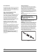
Step 6 Align the flats on the end of the beater assembly with the drive shaft. Make sure the beater assembly locating pin is in position in the locating hole of the drive shaft. Turn the beater slightly to be certain that the beater is properly seated. When in position, the beater will be approximately 3/8” inside the front of the freezing cylinder. Step 7 Before installing the draw valve, slide the two o-rings into the grooves on the draw valve. Lubricate the o-rings and the valve as illustrated below.
Step 9 Snap the draw valve handle onto the door spout. Align the hole in the draw valve with the slot in the draw handle. Figure 17 Step 12 Insert the spring into the front of the door spout. Figure 15 Step 10 Slide the pivot pin through the draw handle and into the draw valve. Figure 18 Step 13 Place the threaded cap on the end of the draw valve cavity. Turn the cap clockwise until it is secure. Figure 16 Step 11 Place the draw handle slide over the opening in the draw handle and the pivot pin.
Step 14 Install the prime plug. Place the two o-rings on the prime plug and lightly lubricate. Step 16 Install the front bearing. Do not lubricate the front bearing. Figure 20 Figure 23 Step 17 Install the freezer door. Position the door on the four studs on the front of the freezing cylinder. Firmly push the door into place. Install the four handscrews on the studs and finger-tighten them equally in a criss-cross pattern to insure that the door is snug. Do not over-tighten the handscrews.
Step 3 Using an empty bag of syrup, cut the syrup line connector from the end of the bag. Sanitizing IMPORTANT: If a unit is sanitized, and will not be used for an extended period of time, clean water should be used to flush all sanitizer from the lines. Remove the water from all the lines and components prior to storage of the unit. Upon return to service, the unit must be sanitized prior to use. Note: The following instructions are for one side of the unit.
Step 5 With the bag connector attached to the syrup line, place the syrup line into the pail of sanitizing solution. Step 8 Pressing the MENU (SEL) key will give you the option for sanitizing the left freezing cylinder. Move the cursor under the word “YES”. Pressing the MENU (SEL) key at this time will start the flow of sanitizing solution into the left freezing cylinder. SANITIZE LEFT SIDE YES --- <- - - -> NO SEL Step 9 Repeat Steps 6 - 8 for the right freezing cylinder.
Step 12 Press the BEATER (- - -) key. Agitate the solution in the freezing cylinders for five minutes. Priming/Brixing Step 1 Connect the syrup line to the Bag-in-Box (BIB) syrup. Step 2 Remove the drip tray, splash shield and the lower front panel to gain access to the syrup sampling valves. Step 3 Open the prime plug. Figure 30 Step 13 With a pail beneath the door spouts, open the draw valves and drain all the solution from the freezing cylinders. Press the OFF (<- -) key and close the draw valves.
Step 5 Press the PRIME (+ + +) key. Step 7 Pour the product from the syrup sampling valve into a cup. Close the syrup sampling valve by turning the handle to the center position. Figure 34 Step 6 Slowly move the syrup sampling valve to the fully open position by turning the handle “down” toward the sampling line. Allow the liquid to run into a pail until all the sanitizer is removed and full strength product is flowing. Figure 36 Step 8 Stir the finished product.
Note: The position of the handle on the syrup sampling valve determines the direction of product flow. The down position opens the syrup sampling valve for collecting brix samples. The center position shuts off the product flow. The up position directs the flow of product to the freezing cylinder. Step 9 To adjust the brix, turn the adjustment screw located behind the drip tray shelf.
Step 15 Close the illuminated display when complete. Replace the panels and the hood, and attach with screws. Install the front drip tray and the splash shield on the front of the freezer. Draining Product From the Freezing Cylinders Step 1 Press the BEATER (- - -) key. This will allow the beater to operate and CO2 pressure will be maintained to push the product from the freezing cylinder. Open the draw valve and drain the product from the machine until the CO2 begins to jet.
Note: There is a left and a right freezing cylinder for each LCD. Rinsing Note: The following instructions are for one pair of freezing cylinders under an LCD. After the instructions are complete, repeat for the two freezing cylinders on the other side of the machine under the other LCD. RINSE RIGHT SIDE Step 7 Repeat these steps for the other side of the machine. SEL Cleaning Note: The following instructions are for one pair of freezing cylinders under an LCD.
Pressing the MENU (SEL) key will give you the option to sanitize the left cylinder. Move the cursor under the word “YES”. Pressing the MENU (SEL) key at this time will start the flow of cleaner/sanitizer through the syrup system into the freezing cylinder. Step 8 With a pail beneath the door spouts, open the draw valves and drain all the solution from the the freezing cylinders. Press the OFF (<- -) key and close the draw valves. Step 9 Repeat these steps for the other side of the machine.
Step 3 Remove the: Brush Cleaning S S Step 1 Prepare a sink or a pail with an approved cleaning solution. USE WARM WATER AND FOLLOW THE MANUFACTURER'S SPECIFICATIONS (examples: Kay-5® or Stera-Sheen®). S S S S S S S S S IMPORTANT: Follow the label directions. Too STRONG of a solution can cause parts damage, while too MILD of a solution will not provide adequate cleaning. Make sure all brushes provided with the freezer are available for brush cleaning.
Section 7 Important: Operator Checklist j 6. Clean and sanitize the syrup lines regularly to prevent syrup residue build-up that would restrict the proper flow of syrup. During Cleaning and Sanitizing ALWAYS FOLLOW LOCAL HEALTH CODES j 7. On a regular basis, take a brix reading to assure a consistent quality product. Cleaning and sanitizing schedules are governed by your State or local regulatory agencies and must be followed accordingly.
Winter Storage If the place of business is to be closed during the winter months, it is important to protect the freezer by following certain precautions, particularly if the building is subject to freezing conditions. Wrap detachable parts of the freezer such as the beater, the scraper blades, the drive shaft, and the freezer door. Place these parts in a protected, dry place. Rubber trim parts and gaskets can be protected by wrapping them with moisture-proof paper.
Section 8 PROBLEM 1. Product is too stiff. Troubleshooting Guide PROBABLE CAUSE REMEDY PAGE REF. 27 a. Too much water to syrup ratio. Improper brix adjustment. a. Adjust the brix accordingly. b. Consistency control needs adjustment. b. Contact a service technician. -- -- -- c. Torque coupling bound in WARM position. c. Contact a service technician. -- -- -- a. Freezer in a defrost cycle. a. Wait for defrost cycle to end. -- -- -- b. Consistency control needs adjustment. b.
PROBLEM PROBABLE CAUSE REMEDY PAGE REF. a. Rounded corners of hex end of drive shaft, drive coupling, or both. a. Replace the drive shaft, or call a service technician to replace the direct drive unit. -- -- -- b. Lubrication of hex end of drive shaft. b. Do not lubricate the hex end. If necessary, contact a service technician for removal. 19 7. Excessive loss of CO2. a. Leak in the CO2 system. a. Contact a service technician. 8. Leakage from rear drip pan(s) into front drip tray. a.
Section 9 PART DESCRIPTION Parts Replacement Schedule EVERY 4 MONTHS Scraper Blade EVERY 8 MONTHS ANNUALLY X Drive Shaft Seal X Drive Shaft O-Ring X Freezer Door O-Ring X Draw Valve O-Ring X Door Spout O-Ring X Front Bearing X Prime Plug O-Ring X Black Bristle Brush, 1” x 2” Inspect & Replace if Necessary Minimum Double Ended Brush Inspect & Replace if Necessary Minimum White Bristle Brush, 1-1/2” x 2” Inspect & Replace if Necessary Minimum White Bristle Brush, 3” x 7” Inspect
Parts List X64892 053377 039349 032511 028992 028991 012864 054579 041182 041103 059590 059589 055437 039422 039423 X59615-27S X64275 091254 040040-019 040040-056 040040-042 040040-058 040040-011 062242-27 049455-27 039976-W5 053957 059755 053197 016137 052397-27E CARD-CHECKOUT SLUSHTECH-5 YR CLAMP-HOSE 23/32-STEPLESS EAR CLAMP-HOSE 15/32-STEPLESS EAR CLIP-RETAINER-LINE-SYRUP *355* +O-RING-3/8 OD X .070 W COMPRESSOR CS17K6E-PFV-238 PART NUMBER ARM A.
+ Available Separately Model C302 39 Parts List +CAPACITOR-RUN 35UF/440V +RELAY-START-COMPRESSOR +CAPACITOR-START 189-227UF/250V COMPRESSOR CS17K6E-PFV-238 CONDENSER-AC 16X29 3ROW 12FPI CORE-SCHRADER VALVE-TEFLON COUPLING A.
+ Available Separately Parts List 40 Model C302 +CAP-SPOUT-DOOR-FCB-BLACK +HANDLE-DRAW-FCB-BLACK +NUT-SPOUT-DOOR-SLUSH-PRESSURE +O-RING-1.129 ODX.989IDX.070W +PIN-PIVOT-SPOUT-DOOR-SLUSH +PLUG-PRIME-SLUSH-PRESSURE +O-RING-9/32 OD X 1/16 WALL +SCREW-10-32X3/8PHL-TRUS HD-SS +SLIDE-HANDLE-DOOR-FCB-BLACK +SPOUT-DOOR-FCB-BLACK +O-RING-1.129 ODX.989IDX.070W +SPRING-COMP.480X.072X3.0-SS +VALVE-DRAW-DOOR-SLUSH-PRESSURE +O-RING-9/16 OD X .
+ Available Separately Model C302 41 Parts List 059622-27 045606 059658 X59121 039349 016369 017003 025307 029751 039219 032560 048260-WHT 023848 032749 053145 051433 042279 039462 059711 051751 X59641 009541 031791 053565 X59640 009541 031791 053565 X62509 016715 049427 R30317 LABEL-WARN-NO DRAW LABEL-WARN-RELIEVE PRESS LED A.-PRODUCT NOT READY LENS-YEL LED-SNAP IN 1/4" HOLE LINE A.-ACCESS-SUCTION-R*C302* FITTING-REDUCER-3/8MS X 1/4FS COUPLING-3/8FS X 1/4FS VALVE-ACCESS-1/4MFL X 3/8ODSDR LINE A.
+ Available Separately Parts List 42 Model C302 LINE A.-CO2 MAN/SOL VLV ADAPTOR-SWV 1/4FFLX1/4 BARB-SS HOSE-BEV.-.250IDX.438OD-100' LINE A.-CO2 SOL VLV/PUMP ADAPTOR-SWV 1/4FFLX1/4 BARB-SS HOSE-BEV.-.250IDX.438OD-100' LINE A.-CO2 WATER ADAPTOR-SWV 3/8FFL X1/4BARB-SS CLAMP-HOSE 1/2-STEPLESS EAR HOSE-BEVERAGE-1/4 ID X 7/16 OD LINE A.
+ Available Separately Model C302 43 Parts List CLAMP-HOSE 1/2-STEPLESS EAR LINE A.-LIQUID *C302*LEFT ELBOW-3/8S-STREET-SHORT RADIUS FITTING-3/8FS X 3/8FS X 3/8FS VALVE-SOL-7/64 ORFX3/8SI-1/4 LINE A.-LIQUID *C302*RIGHT ELBOW-3/8S-STREET-SHORT RADIUS FITTING-3/8FS X 3/8FS X 3/8FS VALVE-SOL-7/64 ORFX3/8SI-1/4SO LINE A.-WATER*INLET*C302* CLAMP-HOSE 23/32-STEPLESS EA FERRULE-.650 ID NP BRASS FITTING-3/8MFLX3/8BARB BULKH HOSE-BEVERAGE-.375 ID X.
+ Available Separately Parts List 44 Model C302 049427 R30313 059438 059364 059437 016715 014477-27B 065681 065682 051284 054631-27 033043 057176 500302-27 500311 043666 013163 043612 059652 059576 059577 059657 059721 059722 X47299-SER X56020-SER X40818 -SER X51169-SER X40872-SER X40873-SER X40875-SER CAPACITOR-START 108-130UF/250V CAPACITOR-RUN 10UF/370V MOTOR A.-FAN 185 WATT 1400RPM CAPACITOR-RUN 4.0UF/400V NUT-STUD *345-346-349-355* PAIL-MIX 10 QT.
+ Available Separately 110405 Model C302 45 Parts List X40876-SER 064254 X45708 038061-BLK 065695 046039 054826 X64892 046039 045912 017329 046046 059603 059616 064363 064376 055526A 051840 023845-27 012725-33 041082 X59648M2 039337 042278 025307 032560 059653 X59578-SER 020445 X59582-SER 020445 059659 REGULATOR-CO2 TANK-DOUBLE RELAY-3PDT-10A-208/240V RELAY-3 POLE-20A-208/240 50/60 SANITIZER KAY-5 CASE 125 PCKTS SENSOR A.
+ Available Separately Parts List 46 Model C302 SHROUD A.-CONDENSER *C302* SWITCH-MEMBRANE-5 POSITION-23" SWITCH-PRESSURE-C02-AU CONTACT SWITCH-PRESSURE-H20-AU CONTACT SWITCH-ROCKER DPST OFF-ON TANK A.-MIX-MOLD CAP-PRESS CAP-TANK-MIX-BOTTOM O-RING-3.875 OD X .139W SCREW-10X7/16 UNSL TD HWH CLIP-RETAINER-TUBE-MIX *C300 SCREW-10X7/16 UNSL TD HWH CAP-TANK-MIX-TOP O-RING-3.875 OD X .139W SCREW-10X7/16 UNSL TD HWH CLIP-RETAINER-LINE-SYRUP-LG SCREW-6X3/8 PHIL. PAN HEAD ORIFICE-FEEDTUBE *C300/C302* O-RING-.
+ Available Separately Model C302 47 Parts List BLOWER-100 CFM +GUARD-BLOWER BRACKET A.
+ Available Separately Parts List 48 Model C302 062082 062098 062082 062098 039423 039421 024156 039424 062013-40 052397-33 052397-40 052399 052400 052401-27 052397-58 059680-37S 059680-40S 059680-58S 064416-DVD 059621-40 COMPRESSOR CS17K6E-PFV-238 COMPRESSOR CS18K6E-PFJ-238 +CAPACITOR-START 145-175UF/25 +CAPACITOR-RUN 45UF/370V +RELAY-START-COMPRESSOR COMPRESSOR CS18K6E-TFD-238 DIAGRAM-WIRING *C302* SINGLPWR DIAGRAM-WIRING *C302* DIAGRAM-WIRING *C302* DVD-OPS TRAIN VIDEO*C300/C302* HARNESS-WIRE-HI VO
+ Available Separately Model C302 49 Parts List X65938-58 054631-40 033043 057176 025569 +CAPACITOR-START 108-130UF/250V +CAPACITOR-RUN 10UF/370V PULLEY-10J- .875PD-1/2BORE 056334-40 056334-58 059651-37 059651-58 014477-40B HARNESS-WIRE-C300 PWR/COMP HARNESS-WIRE *C300* PWR/COMP HARNESS-WIRE-PWR/COMP-L *C302* HARNESS-WIRE-PWR/COMP-L *C302* MOTOR-1/4 HP W/OUT BASE S/N K7097206 & UP *SEE S/N NOTE KIT A.
Model C302 059680-27S Rev.
Model C302 059680-33S Rev.
Model C302 059680-37S Rev.
Model C302 059680-40S Rev.
Model C302 059680-58S Rev.