Model C006 Flavor Dispenser Operating Instructions 066869--M 8/21/08 (Original Publication) (Updated 8/16/12)
Complete this page for quick reference when service is required: Taylor Distributor: Address: Phone: Fax: E-mail: Service: Parts: Date of Installation: Information found on the data label: Model Number: Serial Number: Electrical Specs: Voltage Cycle Phase Maximum Fuse Size: A Minimum Wire Ampacity: A E August, 2008 Taylor (Original Publication) All rights reserved. 066869-M The word Taylor and the Crown design are registered trademarks in the United States of America and certain other countries.
Table of Contents Section 1 Safety . . . . . . . . . . . . . . . . . . . . . . . . . . . . . . . . . . . . . . . . . . . . . . . . . . . . 1 Section 2 To the Installer . . . . . . . . . . . . . . . . . . . . . . . . . . . . . . . . . . . . . . . . . . . . 3 Installing the Flavor Shot Dispenser . . . . . . . . . . . . . . . . . . . . . . . . . . . . . . . . . . . . . 6 Section 3 Operator Parts Identification . . . . . . . . . . . . . . . . . . . . . . . . . . . . . . . 7 Exploded View . . . . . .
Table of Contents - Page 2 Dispensing Flavor Shots - Hot Beverages . . . . . . . . . . . . . . . . . . . . . . . . . . . . . . . . 24 Dispensing Flavor Shots - Box of Coffee . . . . . . . . . . . . . . . . . . . . . . . . . . . . . . . . . 25 Dispensing Flavor Shots - Iced Coffee . . . . . . . . . . . . . . . . . . . . . . . . . . . . . . . . . . . 26 Dispensing Flavor Shots - Latté (Hot or Iced) . . . . . . . . . . . . . . . . . . . . . . . . . . . . . 27 Section 6 Cleaning and Maintenance . . .
Section 1 Safety We at Taylor are concerned about the safety of the operator when he or she comes in contact with the dispenser and its parts. Taylor has gone to extreme efforts to design and manufacture built-in safety features to protect both you and the service technician. As an example, warning labels have been attached to the dispenser to further point out safety precautions to the operator.
DO NOT operate the dispenser unless all service panels and access doors are restrained with screws. Failure to follow this instruction may result in electrocution. Contact your local authorized Taylor Distributor for service. DO NOT operate the dispenser with larger fuses than specified on the dispenser data label. Cleaning and sanitizing schedules are governed by your state or local regulatory agencies and must be followed accordingly.
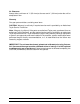
Section 2 To the Installer Overview The flavor shot dispenser Model C006 dispenses nine flavors, combinations of flavors, and liquid sugar products in different volumes. The dispenser is supplied with a cord and grounding type plug. The dispenser is designed for indoor use only. Specifications Capacity: 9 tanks x approximately 1,000 ml. Weight: approximately 65 lbs. (30 kg.), Crated Weight: 74 lbs. (34 kg.) Dimensions: 24” D x 8” W x 25” H Electrical Requirements Electrical Requirements: 120V, AC, 15 amp.
Supply cords used with this unit shall be oil-resistant, sheathed flexible cable not lighter than ordinary polychloroprene or other equivalent synthetic elastomer-sheathed cord (Code designation 60245 IEC 57) installed with the proper cord anchorage to relieve conductors from strain, including twisting, at the terminals and protect the insulation of the conductors from abrasion.
Air Clearance Always allow a minimum of 1” (25.4 mm) at the rear and 4” (102 mm) under the unit for adequate air flow. Warranty One year parts and labor, excluding wear items. CAUTION: Warranty is valid only if required service work is provided by an Authorized Taylor Service Technician. Note: Warranty is valid only if the parts are authorized Taylor parts, purchased from an authorized Taylor Distributor, and the required service work is provided by an authorized Taylor service technician.
Installing the Flavor Shot Dispenser Step Action 1 Place the flavor shot dispenser where it will best serve your operation. 2 Make sure that counters, platforms, and shelves are strong enough to support the weight of the dispenser and full containers of product (109 lbs. [49 kg.]). 3 Maintain a minimum of 1” (25.4 mm) at the rear and 4” (102 mm) under the unit for adequate air flow. 4 DO NOT remove the legs from the dispenser or allow the dispenser to sit directly on the counter.
Section 3 Operator Parts Identification Exploded View ITEM 1 2 3 4 Model C006 DESCRIPTION Switch-Rocker (Power Switch) Tray-Drip Shield A.-Splash Tube A.-Outlet 7 PART NO.
Inside Cabinet View 2 3 1 MAX.
Inside Cabinet View Identification ITEM 1 2 3 DESCRIPTION ABBREVIATION Syrup Tank Cover-Tank Mix Decal-Mag-Instruction ----- PART NO. 062244059133 059532-TAY IMPORTANT: There are nine individual flavor tanks. The tanks must be placed in their proper locations to correspond with current software and display characteristics. All flavors are subject to change at any time.
Section 4 ITEM 1 2 3 4 5 6 7 8 9 10 11 12 13 Important: To the Operator DESCRIPTION Power Switch Flavor Buttons Product Buttons / Calibration Size Buttons / Calibration Promo Portion Button Box of Coffee Button Sugar Button Indicator Lights (LED) LCD Screen Clean/Calibrate Button (Service Menu) Preset Combo Buttons Custom Flavor Button Power Indicator (LED) Important: To the Operator 10 Model C006
Power Switch When the unit is plugged into a receptacle and the power switch is placed in the ON position, the power indicator light will illuminate. The power switch is left in the ON position during normal operations. Selection Buttons Flavor Shot Buttons There are nine flavor shot buttons. When a particular flavor shot is selected, the light above that button will illuminate. Note: All flavors are subject to change at any time.
Flavor Refill and Level Reset When a MIX LOW condition is present, the flavor indicator will flash at 1/2 second intervals and at 1/4 second intervals when a MIX OUT is present. When a MIX OUT condition is present, that specific flavor will lock out until it is refilled and reset. Each flavor can be reset individually at the full or low fill level: Full = HI (586 ml) and Low Fill = LO (195 ml).
Service Display Menu The Service Display Menu provides several screens to the operator and technician for setup, monitoring and evaluation. To enter the Service Display Menu, press the CLEAN/CAL button. The screen will prompt the operator to enter the access code. Use the product size buttons to enter the code as follows: 3 (MED) 2 (SM) 1 (X-SM). Once the Service Display Menu is entered, the following screens are available in the order shown. Cycle through the screens by pressing the CLEAN/CAL button. 1.
Cleaning Flavors and Liquid Sugar Clean Menu Screen The Clean Menu screen allows the operator to clean a maximum of 4 flavors simultaneously, including the sugar. Action Step 1 Press the CLEAN/CAL button. The screen will prompt the operator to enter the access code. Use the size buttons to enter the code as follows: 3 (MED) 2 (SM) 1 (X-SM). 2 Upon entry, the screen will read “CLEAN PRESS FLVR”. 3 Press the flavor button(s) to be cleaned (maximum of 3).
Cleaning All Flavors and Liquid Sugar Clean All Menu Screen The Clean All Menu screen allows the operator to clean all the flavors and the liquid sugar simultaneously. Action Step Model C006 1 Remove the flavor tanks from the unit. 2 Clean the inside of the unit with a clean, damp cloth. 3 Prepare 4 cleaning containers with an approved 100 PPM cleaning/sanitizing solution. 4 Place one container on each shelf with the product tubes in the containers.
Prime All Flavors and Liquid Sugar Prime All Menu Screen The Prime All Menu screen allows the operator to prime all of the flavors, including liquid sugar, simultaneously. Be sure that every flavor, including liquid sugar, being primed has been refilled to the fill line indicated on the tank and the control has been reset (refer to Flavor Refill and Level Reset on page 12. Step Action 1 Press the CLEAN/CAL button. The screen will prompt the operator to enter the access code.
Calibrate Flavors and Liquid Sugar Calibrate Menu Screen The Calibrate Menu screen allows the operator to calibrate and dispense volume for each flavor and liquid sugar. IMPORTANT: Calibration is by weight, NOT volume. Step Action 1 Place a scale under the dispensing spout and place an empty cup on the scale. Reset the scale to “000”. 2 Press the CLEAN/CAL button. The screen will prompt the operator to enter the access code. Use the size buttons to enter the code as follows: 3 (MED) 2 (SM) 1 (X-SM).
Data Menu Data Menu Screen The Data Menu screen allows the operator to view the total number of cycles completed since the last reset for a product flavor combination. Action Step 1 Press the CLEAN/CAL button. The screen will prompt the operator to enter the access code. Use the size buttons to enter the code as follows: 3 (MED) 2 (SM) 1 (X-SM). 2 Upon entry, the screen will read “CLEAN PRESS FLVR”. 3 Press the CLEAN/CAL button five times to display “DATA PRESS PR/FL”.
Section 5 Operating Procedures Assembly and Start Up Step Action 1 Plug the machine into an approved receptacle. The power indicator will illuminate on the front of the dispenser. 2 Open the front door to the dispenser. 3 Remove all tanks and lids. ALWAYS FOLLOW LOCAL HEALTH CODES! Cleaning/Sanitizing Step Model C006 Action 1 Prepare a sink with an approved 100 PPM cleaning/sanitizing solution (example: Kay-5® or Stera Sheen®). USE WARM WATER AND FOLLOW THE MANUFACTURER'S SPECIFICATIONS.
Cleaning/Sanitizing (Continued) Step Action 10 Press the “1” (X-SM) button to begin cleaning. The three flavors corresponding to the top row of flavor keys will clean first. Upon completion, the three flavors in the next row will clean, followed by the three flavors in the last row, and then the SUG (liquid sugar). The cleaning procedure will take approximately four minutes. 11 Remove and discard any cleaning/sanitizing solution remaining in the cleaning containers.
Product Tube Removal/Installation Step Model C006 Action 1 Discard any remaining product in the tank. 2 Wash and rinse the tank and the lid. 3 Fill the tank with clean water to the fill line on the tank. 4 Place a cup under the dispensing spout. Note: Refer to the “Clean Flavors and Liquid Sugar” instructions within the Service Menu on page 14.) 5 Activate the flavor selection corresponding to the product tube in need of replacement. This will pump the water from the tank and tube.
Product Tube Removal/Installation (Continued) Step Action 16 Follow the Break In Flavor instructions starting on page 23 for the flavor line that was replaced. 17 Refer to Cleaning Flavors and Liquid Sugar on page14. Note: To minimize or eliminate any mistakes when replacing and installing a new tube, remove and replace one tube at a time.
Break In Flavor (Product Tube) Model C006 Step Action 1 Prepare a cleaning container with an approved 100 PPM cleaning/sanitizing solution (example: Kay-5® or Stera Sheen®). USE WARM WATER AND FOLLOW THE MANUFACTURER'S SPECIFICATIONS. 2 Remove all three syrup tanks from the shelf containing the tank with the new product tube. 3 Place the cleaning container on the shelf and insert the product tubes in the container.
Dispensing Flavor Shots - Hot Beverages To dispense flavor shots for hot beverages (Coffee, Hot Chocolate), follow these steps: Step Action 1 Select the appropriate cup for the customer's order. 2 Place the cup under the dispensing spout. 3 Press the flavor button. Note: If a combination flavor is desired, first press the CUSTOM button. Then press the desired 2 or 3 flavor buttons. 4 Press the appropriate cup size button. (Pressing the cup size button will dispense the flavor shot product.
Dispensing Flavor Shots - Box of Coffee To dispense the flavor shots for the box of coffee, follow these steps: Model C006 Step Action 1 Place a small coffee cup under the dispensing spout and press the flavor button. 2 Press the Box of Coffee button. This will dispense the proper amount of the flavor shots for the coffee. 3 Place a funnel on the box of coffee. Pour the flavor shots from the coffee cup into the box of coffee. 4 Fill the box of coffee with 108 oz. of coffee.
Dispensing Flavor Shots - Iced Coffee To dispense the flavor shots for Iced Coffee, follow these steps: Step Action 1 Select the appropriate cup for the customer's order. 2 Fill the cup 2/3 full with ice. 3 Place the cup under the dispensing spout. 4 Press the flavor button. 13497 Note: If a combination flavor is desired, first press the CUSTOM button. Then press the desired 2 or 3 flavor buttons. 5 Press the ICE COFF button. 6 Press the appropriate cup size button.
Dispensing Flavor Shots - Latté (Hot or Iced) To dispense the flavor shots for Latté drinks, follow these steps: Step Action 1 Select the appropriate cup for the customer's order. 2 Fill the cup 2/3 full with ice. Note: Skip this step for hot Latté. Model C006 3 Place the cup under the dispensing spout. 4 Press the flavor button. Note: If a combination flavor is desired, first press the CUSTOM button. Then press the desired 2 or 3 flavor buttons. 5 Press the LATTE/CAP button.
Section 6 Cleaning and Maintenance Cleaning Procedure ALWAYS FOLLOW LOCAL HEALTH CODES! To disassemble and clean the unit, the following items will be needed: S Brushes (provided) S Cleaner/Sanitizer (example: Kay-5® or Stera Sheen®) S Single service hand towels Equipment Cleaning and Maintenance Schedule Function Procedure Frequency Initial Flavor Fill Reset the level for each flavor. After cleaning tanks Flavor Refill Reset the level for each flavor.
Section 7 Troubleshooting Guide General Troubleshooting Problem 1. Dispenser will not operate. 2. Dispenser will not dispense product. Model C006 Probable Cause Remedy a. Unit is not plugged in. a. Plug the unit into a receptacle. b. Power switch is in the OFF position. b. Place the power switch in the ON position. The power indicator light will illuminate. a. There is no product in the unit; i.e., there is a MIX OUT condition. a. Add product to the fill line and reset (full or low fill level).
Problem 3. An improper amount of product is being dispensed. Probable Cause Remedy a. Incorrect calibration. a. Re-calibrate. b. The product tube is obstructed or kinked. b. Clear the obstruction or kink. c. The product tube is not properly aligned over the pump rollers. c. Realign the product tube, centering it over the pump rollers and removing any slack. (See page 21.) d. The unit was improperly reset. d. Fill the tank to the fill line and reset (full or low fill level).
Model C006 BOARD-CONTROL-FLAVOR SHOT BRUSH-DBL END-PUMP & FEED BRUSH-DRAW VALVE 1-1/2”OD BRUSH-END-DOOR-SPOUT-SS-H CABLE-INTERFACE/CONTROL *C006* CAP-ULTIMATE SYRUP CORD-POWER-125V-15A-95”LCOVER-TANK MIX *C006* DOOR A.-FRONT *C006* CONTROL-TOUCH SCREEN W/DECAL GASKET-DOOR-FRONT *C006* HINGE-DOOR *C006* HINGE-DOOR *C006* +PLATE A.
100712 + Available Separately Parts List 32 Model C006 TANK-MIX 2 *C006* TANK-MIX 3 *C006* TRAY-DRIP *C006* TUBE A.-OUTLET *C006* TUBE A.-SUCTION-RIGHT *C006 TUBE-PUMP-PERIS-2.4MMIDX2 TUBE A.-SUCTION-MIDDLE *C006 TUBE-PUMP-PERIS-2.4MMIDX2 TUBE A.-SUCTION-LEFT *C006 TUBE-PUMP-PERIS-2.4MMIDX2 TUBE A.-SYRUP PICK UP TUBE-PUMP-PERIS-6.4MMIDX2 DESCRIPTION 062244-11 062244-12 058346 X59334 X59529 067120-10 X59530 067120-10 X59531 067120-10 X53175 059152-60 PART NUMBER 1 1 1 1 3 3 3 3 3 3 1 1 QTY.
Model C006 059359-12 Rev.