OPERATOR’S MANUAL Model 150, 152, 162, & 168 Soft Serve Freezers Original Operating Instructions 028749- M 8/13/08 (Original Publication) Updated 8/6/14
Complete this page for quick reference when service is required: Taylor Distributor: Address: Phone: Service: Parts: Date of Installation: Information found on data plate: Model Number: Serial Number: Electrical Specs: Voltage Cycle Phase Maximum Fuse Size: Amps Minimum Wire Ampacity: Amps Part Number: E 2008 Carrier Commercial Refrigeration, Inc.
Table of Contents Section 1 To the Installer . . . . . . . . . . . . . . . . . . . . . . . . . . . . . . . . . . . . . . . . . . . . 1 Installer Safety . . . . . . . . . . . . . . . . . . . . . . . . . . . . . . . . . . . . . . . . . . . . . . . . . . . . . . . . Site Preparation . . . . . . . . . . . . . . . . . . . . . . . . . . . . . . . . . . . . . . . . . . . . . . . . . . . . . . . Air Cooled Units . . . . . . . . . . . . . . . . . . . . . . . . . . . . . . . . . . . . . . . . . . . . . . . . . . .
Table of Contents - Page 2 Closing Procedure . . . . . . . . . . . . . . . . . . . . . . . . . . . . . . . . . . . . . . . . . . . . . . . . . . . . Draining Product From the Freezing Cylinder . . . . . . . . . . . . . . . . . . . . . . . . . . . . . Rinsing . . . . . . . . . . . . . . . . . . . . . . . . . . . . . . . . . . . . . . . . . . . . . . . . . . . . . . . . . . . . . . Cleaning . . . . . . . . . . . . . . . . . . . . . . . . . . . . . . . . . . . . . . . . . . . . . . . . . . . . . . . . . . . .
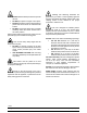
Section 1 To the Installer The following information has been included in the manual as safety and regulatory guidelines. For complete installation instructions, please see the Installation Checklist. This unit has many sharp edges that can cause severe injuries. Installer Safety Site Preparation In all areas of the world, equipment should be installed in accordance with existing local codes. Please contact your local authorities if you have any questions.
Air Cooled Units The models 150 and 152 require a minimum of 6” (152 mm) of clearance around both sides. Install the skirt provided on the right side of the unit and place the back of the unit against a wall to prevent recirculation of warm air. The model 162 requires 6” (152 mm) on all sides and the skirt installed on the rear of the unit. The model 168 requires 3” (76 mm) on all sides and the skirt installed on the rear of the unit.
S S S Electrical connections are made directly to the terminal block provided in the splice box, mounted on the base pan on each side of the model 168, and located in the splice boxes mounted mid- level on the frame channel on the sides of the model 162.
Section 2 To the Operator The freezer you have purchased has been carefully engineered and manufactured to give you dependable operation. The Taylor Company models covered in this manual consist of the following: 150, 152, 162 and 168. compliant with the EU Directive as well as other similar legislation in effect after August 13, 2005. Therefore, it must be collected separately after its use is completed, and cannot be disposed as unsorted municipal waste.
Section 3 Safety We, at Taylor Company, are concerned about the safety of the operator when he or she comes in contact with the freezer and its parts. Taylor has gone to extreme efforts to design and manufacture built- in safety features to protect both you and the service technician. As an example, warning labels have been attached to the freezer to further point out safety precautions to the operator.
S S S S Cleaning and sanitizing schedules are governed by your state or local regulatory agencies and must be followed accordingly. Please refer to the cleaning section of this manual for the proper procedure to clean this unit. DO NOT allow untrained personnel to operate this unit. DO NOT put objects or fingers in door spout. DO NOT operate the freezer unless all service panels and access doors are restrained with screws.
Section 4 Operator Parts Identification Model 150 Figure 1 Item Description Part No. Item Description Part No. 1 Cover A.- Hopper X48690 13 Decal- Decorative- Taylor 047667 2 Tube- Feed- .166 Hole 035819 14 Panel- Upper Side Right 030784- SS 3 Float A.- Mix Level X39690 15 Light- Amber- Round Mix Low 039707 4 Panel- Back Top 050429 16 Caster- 3” Swivel 012227 5 Panel- Upper Side Left 030783- SS 17 Panel A.
Model 152 Figure 2 Item Description Part No. Item Description Part No. 10 Shield- Splash 11- 1/4 x 4- 13/16 025063 1 Cover A.- Hopper X48690 2 Tube- Feed- .166 Hole 035819 11 Tray- Drip 10- 7/8 x 4- 7/16 025062 3 Float A.- Mix Level X39690 12 Decal- Decorative- Taylor 047667 4 Panel- Rear 051556 13 Panel A.
Model 162 Figure 3 Item Description Part No. Item Description Part No. 1 Cover A.- Hopper X37963- SER 11 Tray- Drip- 16- 7/8 x 4- 3/8 030565 2 Tube- Feed- .166 Hole 030797 12 Panel- Front Right 035933- SS 3 Float A.- Mix Level X39690 13 Trim- Front 050212- SS 4 Panel- Rear 047276- SS 14 Panel- Front Left 035932- SS 5 Panel- Side- Left 050213- SS 15 Leg- 4.250” (With O- Ring) 013458 6 Pan- Drip 19- 1/2 Long 035034 16 Panel- Side Right 050214- SS 7 Panel A.
Model 168 Figure 4 Item Description Part No. Item Description Part No. 1 Cover A.- Hopper X37963- SER 12 Panel- Upper Side Right 030784- SS 2 Tube- Feed- .166 Hole SS 030797 13 Insert- Front Panel 030773- SS 3 Float A.- Mix Level X39690 14 Panel A.
Models 150 & 152 Door Assembly Figure 5 Item Description Part No. 1 Valve- Draw 024763 2 O- Ring- 7/8 OD x .103 W 3 O- Ring- 3/4 OD x .103 W 4 Item Description Part No. 8 Door A.- 1 Spout X38959- SER 014402 9 Bearing- Guide 014496 015835 10 O- Ring- 2- 3/4 OD x .139 W 019998 Handle- Draw 024762 11 Bearing- Front 023262 5 Arm- Valve Lifter 024761 12 Beater A. X24689 6 Nut- Stud 034829 13 Seal- U- Cup 080534 7 Cap- Design 1.
Models 162 & 168 Door Assembly Figure 6 Item Description Part No. Item Description Part No. 8 Cap- Design 1.010” ID - 6 Point 014218 1 Valve- Draw 024763 2 O- Ring- 7/8 OD x .103 W 014402 9 Pin A.- Pivot Long X38538 3 Seal- Draw Valve (H- Ring) 030930 10 Valve- Draw- Center 031164 4 Kit A.- Door 3 Spt 1.5 Qt. Valox X56906- SER 11 Bearing- Guide 014496 4a Nut- Stud 056802 12 O- Ring- 2- 3/4 OD x .139 W 019998 5 Pin A.
Models 150 and 152 Accessories Figure 7 Item Description Part No. Item Description Part No. 5 Brush- Mix Pump Body- 3 x 7 White 023316 1 Kit A.- Tune Up X25802 2 Brush- Rear Bearing 1” x 2” 013071 6 Pail- 6 Qt. 023348 3 Brush- Double- Ended 013072 *7 Sanitizer- Stera Sheen See Note 4 Brush- Draw Valve 1 OD x 2 x 17 013073 8 Lubricant- Taylor 4 Oz. 047518 *Note: A sample container of sanitizer is sent with the unit. For reorders, order Stera Sheen part no. 055492 (100 2 oz.
Models 162 and 168 Accessories Figure 8 Item Description Part No. 1 Kit A.- Tune Up X31167 2 Brush- Rear Bearing 1” x 2” 3 Brush- Double Ended 4 Brush- Draw Valve 1” x 2” x 17” Item Description Part No. 5 Brush- Mix Pump Body- 3” x 7” 023316 013071 6 Pail- 6 Qt. 023348 013072 *7 Sanitizer See Note 013073 8 Lubricant- Taylor 4 Oz. 047518 *Note: A sample container of sanitizer is sent with the unit. For reorders, order Stera Sheen part no. 055492 (100 2 oz.
Section 5 Important: To the Operator Figure 9 Item 1 2 3 4 5 The following chart identifies the symbol definitions used on the operator switches. Description Reset Button Power Switch Temperature Control Mix Refrigeration Switch Indicator Lights - “Mix Low” = ON/AUTO key = ON key = OFF key Symbol Definitions = WASH key To better communicate in the International arena, the words on many of our operator switches and buttons have symbols to indicate their functions.
Reset Button Taylor Quality Control If an overload condition occurs, the freezer will automatically stop operating. To properly reset the freezer, place the toggle switch in the “OFF” position. Wait two or three minutes; then press the reset button. Place the power switch in the “WASH” position and observe the freezer’s performance; place the power switch in the “AUTO” position. These units use a solid state control called the T.Q.C.
Cylinder Temperature Retention (CTR) To operate the “STANDBY” mode of operation: Place the power switch in the “AUTO” position and the mix refrigeration switch in the “STANDBY” position. With sanitized hands, remove the feed tube. Turn it over and place the end without the hole into the mix inlet hole. To maintain a good quality product during long “No Sale” periods, it will be necessary to warm the product in the freezing cylinder to approximately 35_ to 40_F (1.7_ to 4.4_C).
Section 6 Operating Procedures The Model 150 has been selected to illustrate the pictured step- by- step operating procedures. All models in this manual are similar. They each have a 1.5 quart (1.4 liter) capacity freezing cylinder. The mix flows by gravity from the hopper to the freezing cylinder through an feed tube. The Model 150 is a console model with a single spout door. The Model 152 is a counter model with a single spout door. The Model 162 is a counter model and the Model 168 is a console model.
Assembly Step 3 Place the large o- ring(s) into the groove(s) on the back of the freezer door and lubricate with Taylor Lube. Note: When lubricating parts, use an approved food grade lubricant (example: Taylor Lube). Step 1 Lubricate the groove on the beater drive shaft. With the opening of the cup seal facing away from the hex end, slide the seal into the groove. Apply an even coat of lubricant to the seal and the shaft. Do not lubricate the hex end of the beater drive shaft.
Step 7 Finger- tighten the handscrews, making sure they are tightened equally and that the door is snug. Do not over- tighten the handscrews. Step 9 Lubricate the inside of the freezer door spout(s) from the bottom. Insert the draw valve(s) into the freezer door from the bottom. IMPORTANT! Handscrew and door damage can result if the handscrews are over- tightened or if one handscrew is tightened more than the other.
Step 10 Insert the valve lifter arm through the slotted opening in the draw valve and align the other end with the cross holes of the freezer door. Step 12 Insert the draw valve handle through the opposite cross hole and into the opening of the valve lifter arm. Hint: The draw valve handle can be assembled at varied vertical positions. Choose an angle which is comfortable for you. The draw valve must be raised completely when the draw valve handle is down.
Sanitizing Note: Models 162/168 have three draw handles. Slide the tip of the draw handle into the slot of the draw valve, starting from the right. Slide the short pivot pin through the far right draw handle. Slide the long pivot pin through the far left and middle draw handles. Step 1 Prepare an approved 100 PPM sanitizing solution (examples: Kay- 5R or Stera- SheenR). USE WARM WATER AND FOLLOW THE MANUFACTURER’S SPECIFICATIONS. Step 2 Pour one gallon (3.
Step 6 Place an empty pail beneath the door spout and raise the draw valve. Draw off all of the sanitizing solution. When the sanitizer stops flowing from the door spout, lower the draw valve and place the power switch in the “OFF” position. Figure 31 Step 4 Press the reset button. Figure 34 Note: On Models 162/168, momentarily pull down the center draw handle to sanitize the center door spout. Step 7 With sanitized hands, stand the feed tube in the corner of the mix hopper.
Priming Step 3 Momentarily raise the draw switch paddle to activate the refrigeration cycle. Place the power switch in the “AUTO” position. When the unit cycles off, the product will be ready to serve. Prime the machine as close as possible to the time of first product draw. Step 1 With a pail beneath the door spout, raise the draw valve. Fill the mix hopper with fresh mix. (Maximum hopper capacity is 8 quarts [7.6 liters].) Allow the mix to flow into the freezing cylinder.
Step 6 Slide the rear drip pan into the hole in the side panel. Note: If local health codes DO NOT permit the use of rerun, the product must be discarded. Follow the instructions in the previous step, except drain the product into a pail and properly discard the mix. ALWAYS FOLLOW LOCAL HEALTH CODES. Repeat Steps 1 through 3 for the second freezing cylinder on Models 162/168. Rinsing Step 1 Pour one gallon (3.8 liters) of cool, clean water into the mix hopper.
Step 5 Place an empty pail beneath the door spout and raise the draw valve. Draw off all the cleaning solution. When the solution stops flowing from the door spout, lower the draw valve and place the power switch in the “OFF” position. Repeat Steps 1 through 5 for the other side of the freezer on Models 162/168. Note: To remove the o- rings, use a single service towel to grasp the o- ring. Apply pressure in an upward direction until the o- ring pops out of its groove.
Section 7 Important: Operator Checklist During Cleaning and Sanitizing j 5. IF LOCAL HEALTH CODES PERMIT THE USE OF RERUN, make sure the mix rerun is stored in a sanitized, covered stainless steel container and is used the following day. DO NOT prime the machine with rerun. When using rerun, skim off the foam and discard. Mix the rerun with fresh mix in a ratio of 50/50 during the day’s operation. ALWAYS FOLLOW LOCAL HEALTH CODES.
Winter Storage j 5. If your machine is air cooled, check the condenser for an accumulation of dirt and lint. A dirty condenser will reduce the efficiency and capacity of the machine. Condensers should be cleaned monthly with a soft brush. Never use screwdrivers or other metal probes to clean between the fins. Failure to comply may result in electrocution. Note: For machines equipped with an air filter, it will be necessary to vacuum clean the filters on a monthly schedule.
Section 8 PROBLEM 1. No product being dispensed. 2. The machine will not operate in the “AUTO” mode. 3. The product is too stiff. Models 150, 152, 162, 168 Troubleshooting Guide PROBABLE CAUSE REMEDY PAGE REF. a. The power switch is in the “OFF” position. a. Place the power switch in the “AUTO” position. 24 b. The mix level is inadequate in the mix hopper. b. Fill the mix hopper with mix. 24 c. The beater motor overloaded. c. Reset the freezer. 16 d.
PROBLEM 4. The product is too soft. 5. The freezing cylinder walls are scored. 6. Excessive leakage in rear drip pan. 7. The draw valve is leaking. 8. Product is not feeding into the freezing cylinder. Troubleshooting Guide PROBABLE CAUSE REMEDY PAGE REF. a. The temperature control or the T.Q.C. is set too warm. a. Adjust the temperature control. If T.Q.C., contact service technician. 16 b. The feed tube is not installed. b.
PROBLEM 9. The unit goes out on overload excessively. 10. Models 162 and 168: Mix from one freezing cylinder bleeds over to the second cylinder. Models 150, 152, 162, 168 PROBABLE CAUSE REMEDY PAGE REF. a. There are too many appliances plugged into the circuit. a. A separate 20 amp. circuit is needed for the freezer to operate properly. - - - b. An extension cord has been placed between the power cord and the wall receptacle. b.
Section 9 PART DESCRIPTION Parts Replacement Schedule EVERY 3 MONTHS EVERY 6 MONTHS ANNUALLY QTY.
Section 10 Limited Warranty on Equipment TAYLOR COMPANY LIMITED WARRANTY ON FREEZERS Taylor Company, a division of Carrier Commercial Refrigeration, Inc. (“Taylor”) is pleased to provide this limited warranty on new Taylor-branded freezer equipment available from Taylor to the market generally (the “Product”) to the original purchaser only. LIMITED WARRANTY Taylor warrants the Product against failure due to defect in materials or workmanship under normal use and service as follows.
3. Replacement of wear items designated as Class “000” parts in the Taylor Operator’s Manual. 4. External hoses, electrical power supplies, and machine grounding. 5. Parts not supplied or designated by Taylor, or damages resulting from their use. 6. Return trips or waiting time required because a service technician is prevented from beginning warranty service work promptly upon arrival. 7.
Section 11 Limited Warranty on Parts TAYLOR COMPANY LIMITED WARRANTY ON TAYLOR GENUINE PARTS Taylor Company, a division of Carrier Commercial Refrigeration, Inc. (“Taylor”) is pleased to provide this limited warranty on new Taylor genuine replacement components and parts available from Taylor to the market generally (the “Parts”) to the original purchaser only. LIMITED WARRANTY Taylor warrants the Parts against failure due to defect in materials or workmanship under normal use and service as follows.
LIMITED WARRANTY EXCEPTIONS This limited warranty does not cover: 1. Labor or other costs incurred for diagnosing, repairing, removing, installing, shipping, servicing or handling of defective Parts, replacement Parts, or new Parts. 2. Normal maintenance, cleaning and lubrication as outlined in the Taylor Operator’s Manual, including cleaning of condensers or carbon and grease buildup. 3.
LIMITATION OF WARRANTY THIS LIMITED WARRANTY IS EXCLUSIVE AND IS IN LIEU OF ALL OTHER WARRANTIES, CONDITIONS AND/OR REMEDIES UNDER THE LAW, INCLUDING ANY IMPLIED WARRANTIES OR CONDITIONS OF MERCHANTABILITY OR FITNESS FOR A PARTICULAR PURPOSE. THE ORIGINAL OWNER’S SOLE REMEDY WITH RESPECT TO ANY PRODUCTS SHALL BE REPAIR OR REPLACEMENT OF DEFECTIVE PARTS UNDER THE TERMS OF THIS LIMITED WARRANTY.
023262 014496 023648 025564 023647 025027 024764 X24689 080534 041137 025776 025551 028182 039421 039422 024329 025156 013072 013073 023316 013071 014218 012226 012227 049302023739 039557-27 045432-12 027087 039567 048150 047701- BEARING-GUIDE BEARING-REAR SHELL *150-52-68* +COLLAR-REAR BEARING +NUT-REAR BEARING *150-52-68* +TAB-BEARING LOCK *150-2-68* BEARING-UNIT REAR BEATER A.
+ Available Separately Models 150, 152, 162, 168 39 Parts List +RELAY-START-COMPRESSOR +RELAY-START-COMPRESSOR-TL3G +CAPACITOR-START-60UF-220/275V CONDENSER-AC-7X6X1.25-2 ROW CONDENSER-AC-12LX14HX1.87T 3RW CONDENSER-AC-9HX24WX2.5T-4 ROW CONDENSER-AC-15LX14HX2.57-4R CONTROL-TEMP. CONTROL-VISCOSITY-WATT CONTROL-VISCOSITY-WATT CORD-POWER CORD-POWER COVER A.-HOPPER *M150-152 COVER A.-HOPPER *162-168* KNOB-MIX COVER DAMPER A.-FOR USE ON 25W ONLY DECAL-CLEAN INST.
110517 + Available Separately Parts List 40 Models 150, 152, 162, 168 048894 047699 048255 048901 037665-DVD X39690 037042 025770-SER 025496 035548 X28593 X50224 035866 X49063 X49065 X35918 X34846 030564 019998 X38538 016272 X38539 016272 024763 014402 031164 030930 X30753-SER +HANDLE-DRAW VALVE +O-RING-2-3/4 OD X .139W +PIN A.-PIVOT-LONG +O-RING-5/16 OD X .070W +PIN A.-PIVOT-SHORT +O-RING-5/16 OD X .070W +VALVE-DRAW *150-2* +O-RING-7/8 OD X .103W +VALVE-DRAW -CENTER +SEAL-DRIVE SHAFT DOOR A.
+ Available Separately 120501 Models 150, 152, 162, 168 41 Parts List INSERT-FRONT PANEL *168* LABEL-CAUTION-GRD-PERM-ENG/SP LABEL-CAUTION GROUND CORD UNIT LABEL-DOOR CAUTION LABEL-MIX COOLING ADJ. LABEL-MOVING PARTS WARNING LABEL-STD BY BARREL TEMP ADJ LEG-4"-3/8-16 STUD-PLASTIC LEG-4" SS-W/ORING LIGHT-MIX LOW-AMBER ROUND-12V LUBRICANT-TAYLOR 4 OZ. KIT A.-TUNE UP*150-152* CAP-DESIGN-1.010"ID-6 POINT O-RING-7/8 OD X .103W BEARING-GUIDE O-RING-3/4 OD X .103W O-RING-2-3/4 OD X .
+ Available Separately Parts List 42 Models 150, 152, 162, 168 046568 024839027309027817028405 027818 015184047231 029770-27 047279 056802 034829 023348 027503 035034 027504 X25036 X25518 050430 050429 025533-SS 030792-SS 030783-SS 030784-SS 051556 MOTOR-FAN 17W/60HZ 2900RPM-CCW MOTOR-FAN 35W-40"LEADS +FAN-4 BLADE 11 " PULL 30DEG CW +FAN-4 BLADE 11 " PUSH 30DEG CW MOTOR-FAN-25W +FAN-5 BLADE 8" PUSH 37 DEG CCW MOTOR-FAN 50 WATT W/GROUNDWIRE +FAN-5 BLADE 12"PUSH 32DEG CCW NUT-STUD *161-162-168* NUT-STU
+ Available Separately 110804 Models 150, 152, 162, 168 43 Parts List PANEL-SIDE *152*LEFT*HP62 PANEL-SIDE *152*RIGHT*HP62* PANEL A.-CONTROL LEFT *162* PANEL A.-CONTROL RIGHT *162* PANEL A.-FRONT *162-168 PANEL-FRONT LEFT *162* PANEL-FRONT RIGHT *162* PANEL-REAR *162AC* PANEL-SIDE-LEFT-162 PANEL-SIDE-RIGHT-162 PANEL A.
+ Available Separately Parts List 44 Models 150, 152, 162, 168 SHELL A.-INSULATED *162/168* STUD-NOSE CONE-5/16-18X5/16-18 SHIELD-SPLASH 11-1/4 X 4-13/16 SHIELD-SPLASH *162-168* SHROUD A.-CONDENSER *150*UPPER SHROUD A.-CONDENSER *168*AIR SHROUD-CONDENSER *150* SHROUD-CONDENSER *150*FRT/LEFT SHROUD-CONDENSER *150*FRT/RT SHROUD-CONDENSER *152* SHROUD-CONDENSER SHROUD-DANFOSS SHROUD-DANFOSS SHROUD-REAR SKIRT-AIR FLOW *162*HP62 SKIRT-AIR FLOW *162/168* SWITCH A.
+ Available Separately Models 150, 152, 162, 168 45 Parts List 035609 048230 052663 016530 014464 017184 026686 X31959031958030667037188010246025062 030565 025537 025528 025536 025862-SS 025866 050212-SS 035923 030795 030775 030774 035819 030797 044455 047016 046903 044404 053565 022665 SWITCH-PUSHBUTTON-SPST SWITCH-TOGGLE-DPDT*ON-OFF-ON SWITCH-TOGGLE-3PDT TEE-ACCESS 1/4 TIMER A.-CYCLE-14 MIN TIMER-DELAY ON MAKE-30-1000S TIMER-DELAY ON MAKE 2 SEC. TIMER-CYCLE-5 SEC ON/120 SEC OFF TRANS.-CONT.
+ Available Separately Parts List 46 Models 150, 152, 162, 168 KIT A.-HOPPER LOCK-162 BAR-HOPPER LOCK *162* LOCK-ADJ SHACKLE PADLOCK TYPE NUTSERT-10-32/.020-.130 GRIP RETAINER-BAR-LOCK-HOPPER RETAINER-BAR-LOCK-HOPPER-ADJ SCREW-10-32X1-1/2 SLTD TRUSS STANDOFF-3/8"L X 1/2"D SS DECAL-MAG-FLAVOR PADS DECAL-MAG-SLF SRV-TM-TWIN GUARD-POWER SWITCH GUARD-POWER & DANFOSS SWITCHES PCB A.
N 1 2 3 NC NO NC WHT BLK FIG.
L1 L2 OR N 1 2 3 4 NC NO NC NO BLK FIG. 4 BLK CORD C C 9 8 7 3 5 2 4 1 L1 T1 MAIN COMPRESSOR CONTACTOR NO NC NO NC NO NC WHT/BRN HPCO SWITCH BLK CORD BLK M M WHT BLACK/CORD MAIN COMPRESSOR (FIG. 1) 5 4 3 2 1 5 4 WHT/BLK YEL T2 WHT BRN L2 A 1 4 2 WASH OFF AUTO WHT 1 3 WHT 2 5 GRN/YEL L1 2 L2 1 3 4 6 AUTO OFF PRP/WHT STANDBY AUTO OFF STANDBY WHT WHT/RED GRN/YEL RED (INTERNAL) BLK (INTERNAL) BRN A. O. SMITH .
N EQUIPOTENTIAL GROUND 1 NC NO NC M M 3 2 1 WHT BLK/CORD T2 L2 GRN/YEL BLU RED/WHT A MAIN COMPRESSOR CONTACTOR BLU BLK BLK CORD MAIN COMPRESSOR (FIG.
L1 LEFT POWER SUPPLY N WHT WHT BLK BLK 13 L1 BLK LEFT MAIN COMPRESSOR CONTACTOR WHT/ORN 14 T1 WHT M T2 WHT WHT L2 LEFT MAIN COMPRESSOR CONTACTOR LEFT MAIN COMPRESSOR (FIG. 3) BLK CORD BLK LEFT MAIN COMPRESSOR CONTACTOR WHT/GRA13 WHT BLK CORD M MAIN CONDENSER FAN (ONE (1) FAN MOTOR ONLY FOR MODEL 168. RUN CAPACITOR APPLIES TO MODEL 168 ONLY.
NOTES: 1. ONE (1) FAN ONLY ON MODEL FIG. 1 168. RUN CAPACITOR APPLIES TO MODEL 168 ONLY. START RELAY (047702-27) START CAPACITOR (047703) 11 L1 10 13 12 14 L2 STANDBY TEMP CONTROL START WINDING 3PDT MAIN WINDING (L) SHR SW. WINDING PROTECTOR (INTERNAL) STANDBY BLACK/WHITE STRIPE 8 PURPLE/WHT STR 9 COMPRESSOR WIRING (MODEL TL3G W/HST) WHITE/BLK STR BROWN/WHT STR AUTO 7 STANDBY 6 WHITE/GRAY STR COMP. (SEE FIG. 1) TEMP.
L1 N POWER SUPPLY GRN/YEL GRN/YEL BLK L1 T1 BLK LEFT MAIN COMPRESSOR CONTACTOR BLK M T2 WHT BLK L2 GRN/YEL WHT BLK CORD M GRN/YEL MAIN CONDENSER FAN (ONE (1) FAN MOTOR ONLY FOR MODEL 168. RUN CAPACITOR APPLIES TO MODEL 168 ONLY.) LEFT MAIN COMPRESSOR CONTACTOR LEFT MAIN COMPRESSOR (FIG.