
User's Manual


2
Models 345, 346, 349, 355To the Installer
120828
Water Cooled Refrigeration Units
(Water Cooled Units Only)
Failure to use adequate size water lines may cause the
unit to go off on high head pressure and shut down.
Depending on local water conditions, it may be
advisable to install a water strainer to prevent foreign
substances from clogging the automatic water valve.
There are two water “in” connections and one water
“out” line connection. DO NOT install a hand shut-off
valve on the water “out” line! Water should always
flow in this order: first, through the automatic water
valve; second, through the condenser; and third,
through the outlet fitting to an opentrapdrain.
IMPORTANT: Water pressures are pre-set at the
factory. Do not adjust the water. Improper water
adjustments may cause operation discrepancies.
A back flow prevention device is required
on the incoming water connection side. Please
refer to the applicable National, State, and local codes
for determining the proper configuration.
Water Connections
An adequate cold water supply must be provided
with a hand shut-off valve. On the back of the unit, a
3/8” (9.5 mm) M.F.L. water connection has been
provided for easy hook-up. A flexible line is
recommended, if local codes permit. A minimum of
25 psi water pressure is required to avoid having the
unit cut out the low water pressure switch. A booster
pump must be provided if this pressure is not
available.
Note: W ater lines beyond 200 ft. (61 m) require 1/2”
(13 mm) water lines.
INSTALL POTABLE WATER CONNECTION
WITH ADEQUATE BACK-FLOW
PROTECTION TO COMPLY WITH
APPLICABLE NATIONAL, STATE AND
LOCAL CODES.
It is always a good practice to have a filter system to
improve the quality of the water and to avoid
clogging the operating components.
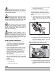
IMPORTANT: The water filter (064422- SER) must
be thoroughly flushed with water before connecting it
to the machine. This removes carbon particles that
could clog the flow control. To flush the filter,
connect the inlet end of the filter to the water supply.
Position the outlet end of the filter over an empty
pail. Open the water supply. Allow water to flow
through the filter until the water exiting the filter is
clear . Close the water supply. Attach the outlet end
of the filter to the machine. Reopen the water
supply.
Figure 1
Electrical Connections
In the United States, this equipment is intended to be
installed in accordance with the National Electrical
Code (NEC), ANSI/NFPA 70- 1987. The purpose of
the NEC code is the practical safeguarding of persons
and property from hazards arising from the use of
electricity. This code contains provisions considered
necessary for safety. Compliance therewith and
proper maintenance will result in an installation
essentially free from hazard! In all other areas of the
world, equipment should be installed in accordance
with the existing local codes. Please contact your local
authorities.
FOLLOW YOUR LOCAL ELECTRICAL CODES!
Each unit requires one power supply for each data
label on the unit. Check the data label(s) on the freezer
for branch circuit overcurrent protection or fuse, circuit
ampacity, and other electrical specifications. Refer to
the wiring diagram provided inside of the control box
for proper power connections.