OPERATOR'S MANUAL Model C043 Frozen Custard Machine Original Operating Instructions 068359- M 7/22/10 (Original Publication) (Updated 11/22/13)
Complete this page for quick reference when service is required: Taylor Distributor: Address: Phone: Service: Parts: Date of Installation: Information found on the C043 data label: Model Number: Serial Number: Electrical Specs: Voltage Cycle Phase Maximum Fuse Size: Amps Minimum Wire Ampacity: Amps Part Number: Information found on RC35 data label: Model Number: Serial Numbers: Electrical Specs: Voltage Cycle Phase Maximum Fuse Size: Amps Minimum Wire Ampacity: Amps E 2010 Carrier Commercial R
Table of Contents Section 1 To the Installer . . . . . . . . . . . . . . . . . . . . . . . . . . . . . . . . . . . . . . . . . . . . 1 Section 2 To the Operator . . . . . . . . . . . . . . . . . . . . . . . . . . . . . . . . . . . . . . . . . . . 4 Section 3 Safety . . . . . . . . . . . . . . . . . . . . . . . . . . . . . . . . . . . . . . . . . . . . . . . . . . . . 5 Section 4 Operator Parts Identification . . . . . . . . . . . . . . . . . . . . . . . . . . . . . . . 8 C043 . . . . . . . . . .
Table of Contents - Page 2 Section 10 Limited Warranty on Equipment . . . . . . . . . . . . . . . . . . . . . . . . . . . . 40 Section 11 Limited Warranty on Parts . . . . . . . . . . . . . . . . . . . . . . . . . . . . . . . . . 42 Section 12 Parts List . . . . . . . . . . . . . . . . . . . . . . . . . . . . . . . . . . . . . . . . . . . . . . . . . 45 Wiring Diagrams . . . . . . . . . . . . . . . . . . . . . . . . . . . . . . . . . . . . . . . . . . . . . . . . . . . . . .
Section 1 To the Installer The following information has been included in the manual as safety and regulatory guidelines. For complete installation instructions, please see the Installation Checklist. This unit has many sharp edges that can cause severe injuries. Installer Safety Site Preparation Review the area where the unit will be installed before uncrating the unit. Make sure all possible hazards to the user or equipment have been addressed.
This unit must be installed on a level surface to avoid the hazard of tipping. Extreme care should be taken in moving this equipment for any reason. Two or more persons are required to safely move this unit. Failure to comply may result in personal injury or equipment damage. DO NOT operate this freezer with larger fuses than specified on the unit's data label. Failure to follow this instruction may result in electrocution or damage to the machine. Uncrate the unit and inspect it for damage.
Beater Rotation Refrigerant liquid sprayed onto the skin may cause serious damage to tissue. Keep eyes and skin protected. If refrigerant burns should occur, flush immediately with cold water. If burns are severe, apply ice packs and contact a physician immediately. Beater rotation must be counter-clockwise as viewed looking into the freezing cylinder. Note: The following procedures should be performed by a trained service technician.
Section 2 To the Operator Your freezer has been carefully engineered and manufactured to give you dependable operation. use is completed, and cannot be disposed as unsorted municipal waste. This unit, when properly operated and cared for, will produce a consistent quality product. Like all mechanical products, it will require cleaning and maintenance. A minimum amount of care and attention is necessary if the operating procedures outlined in this manual are followed closely.
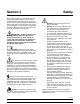
Section 3 Safety We at Taylor Company are concerned about the safety of the operator when he or she comes in contact with the freezer and its parts. Taylor has gone to extreme efforts to design and manufacture built-in safety features to protect both you and the service technician. As an example, warning labels have been attached to the freezer to further point out safety precautions to the operator.
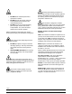
S DO NOT allow untrained personnel to operate this machine. S DO NOT operate the freezer unless all service panels and access doors are restrained with screws. S DO NOT remove any internal operating parts (example: freezer door, beater, scraper blades, etc.) unless all control switches are in the OFF position. Cleaning and sanitizing schedules are governed by your state or local regulatory agencies and must be followed accordingly.
Notes: Model C043 7 Safety
Section 4 Operator Parts Identification C043 Figure 1 Operator Parts Identification 8 Model C043
Exploded View Parts Identification ITEM DESCRIPTION PART NO. ITEM DESCRIPTION PART NO. 1 TRAY A.-DRIP X63636 10 PANEL A.-SIDE RIGHT X63720 2 COVER-HOPPER-FRONT INS 065701 11 LEG-8” 2”OD-3/4-10 STUD-HEX 044652 3 COVER-HOPPER-REAR INS 065700 12 SCREW-1/4-20 X 3/8 PHIL TRUS 038872 4 LEVER A.-FLOW REG X64316 13 HANDLE-STNLS FLUSH PULL 019043 5 ROD-FLOW CONTROL 063593 14 CHUTE-LONG 063619 6 TUBE A.-FEED PLASTIC X67453 15 CHUTE-SHORT 063618 7 PANEL A.
Beater Door & Hopper Assemblies Figure 2 110207 Operator Parts Identification 10 Model C043
Beater Door & Hopper Assemblies Parts Identification ITEM DESCRIPTION PART NO. ITEM DESCRIPTION PART NO. 1 CHUTE-SHORT 063618 9 SPRING-DASHER BLADE 063693 2 DOOR A. C043 X63611-SER 10 BLADE-SCRAPER-REAR 063640 3 NUT-STUD 043666 11 SHAFT A.-DASHER X63689 4 PLATE-DRAW ARM 063614 12 SEAL-DRIVE SHAFT 032560 5 NUT-STUD 034383 13 TUBE A.
Accessories Figure 3 ITEM DESCRIPTION 1 BRUSH-DBL END-PUMP & FEED 2 PART NO. ITEM DESCRIPTION 013072 7 TOOL-DASHER SHAFT REMOVE 063623 BRUSH-DRAW VALVE 1”OD X 2”X17” 013073 **8 SANITIZER SEE NOTE KIT A.-TUNE UP X64743 *3 BRUSH-BARREL 063843 10 RAKE-BLADE GUARD 064888 *4 BRUSH-REAR BRG 063844 11 TIMER-COUNTDOWN-DIGITAL 065425 5 BRUSH-MIX PUMP BODY 3”X7” 023316 12 CHUTE-LONG 063619 6 BRUSH-END-DOOR-SPOUT-SS 039719 9 PART NO.
Section 5 Important to Operator Figure 4 ITEM Flow Adjustment Knob DESCRIPTION 1 HOPPER REFRIGERATION SWITCH 2 OPERATIONAL REFRIGERATION SWITCH 3 FLOW ADJUSTMENT KNOB 4 MIX LOW INDICATOR LIGHT 5 BEATER MOTOR SWITCH 6 DIGITAL COUNTDOWN TIMER The flow adjustment knob adjusts the flow of product into the freezing cylinders. Note: Whenever an adjustment is made, first turn the adjustment knob all the way to “5” and then back to the desired number.
Section 6 Operating Procedures This machine is a three flavor custard freezer. It has three 30 quart (28 liter) hoppers. The mix flows by gravity through an adjustable flow control into the freezing cylinders. This unit has been designed to produce a rich tasting custard product that can be drawn off and served from a holding cabinet. The overrun is typically 20-25% and varies depending on the mix formulation and the finished product temperature (18 to 21°F [-7.8 to -6.1°C]).
Step 5 Lubricate the beater shaft. IMPORTANT! DO NOT lubricate the hex end of the beater shaft. Step 3 Slide the seal over the shaft and groove until it snaps into place. Figure 7 Figure 9 Step 4 Fill the inside portion of the seal with 1/4” (6 mm) more lubricant and lubricate the flat side of the seal that fits onto the rear shell bearing. Step 6 Inspect each scraper blade for any nicks or signs of excessive wear. If any nicks or signs of wear are present, replace the blade.
Step 7 Starting at the hex end of the beater shaft, place a metal leaf spring (arched upward) over the two pins closest to that end. Install the long scraper blade on top of the leaf spring. (Note: There is only one long scraper blade per beater.) Step 11 Continue adding leaf springs and short scraper blades to the beater shaft until all 12 blades are installed. Step 12 Slide the beater shaft into the freezing cylinder, rotating the beater shaft slightly counter-clockwise.
Door Assembly Step 1 With the door in a horizontal position, install the draw arm plate. Install all three short stud nuts and leave them loose. Figure 16 Step 4 Seat the door on the freezer studs. To ensure the door gasket doesn't fall off, hold the door flush with the freezing cylinder with one hand while installing the stud nuts with the other hand. Hand-tighten the stud nuts equally in a criss-cross pattern to insure the door is snug. Figure 15 Step 2 Turn the door over and install the door gasket.
Sanitizing Step 1 Using lukewarm water, prepare an approved 100 PPM sanitizing solution (examples: 5 gal. [19 liters] of Kay-5R or 4 gal. [15 liters] of Stera-SheenR). USE WARM WATER AND FOLLOW THE MANUFACTURER'S SPECIFICATIONS. Step 2 Place the feed tube and the flow control rod flat on the bottom of the hopper. Figure 20 Step 5 Attach the splash guards to the door studs. Figure 18 Figure 21 Step 3 Place the product chutes in the hopper.
Step 10 Place the beater switch in the ON position and set the timer for five minutes. Step 7 Place an empty mix pail under the draw arm plate (if the machine is not equipped with a trough). Figure 23 Step 8 Pour the sanitizing solution into the hopper. Figure 26 Step 11 After five minutes have elapsed, open the draw arm plate and drain the sanitizer into the empty mix pail. Note: If your machine is equipped with a trough, drain the sanitizer into the trough.
Step 15 Install the feed tube assembly into the mix inlet hole located at the bottom of the hopper. Make sure the feed tube is completely seated in the mix inlet hole. IMPORTANT! Your hands must be clean and sanitized before proceeding with the next steps. Step 13 Remove the splash guards from the doors. Figure 30 Step 16 Place one end of the flow control rod into the hole located on the feed tube. Place the other end of the rod into the hole on the front flow control lever.
Step 2 On the front half of the hoppers, install the hopper covers that have the raised lip. Priming KEEP FINGERS OUT OF FILL AND DISCHARGE OPENINGS! Failure to do so may result in severe personal injury, contaminated product, or component damage. Step 1 IMPORTANT: Verify that the flow adjustment knob is in the “CLOSE” position and the beater motor switch is in the “OFF” position. The draw arm plate must be closed.
Step 5 On the back half of the hoppers, install the hopper covers that have the concave lip. For maximum capacity, the hopper should be full. Step 7 After one minute has expired, turn the flow adjustment knob to “1” and set the timer for three minutes. Note: Whenever an adjustment is made, first turn the adjustment knob all the way to “5” and then back to the desired number. Figure 37 Figure 35 Step 6 Place the beater switch and the refrigeration switch in the “ON” position. Set the timer for one minute.
Step 12 When the desired amount is obtained and more custard will be made later, follow the “Hold Cycle During Operation” instructions starting on page 23. Step 10 Open the draw arm plate. Step 13 Repeat these steps for the remaining freezing cylinders. Hold Cycle During Operation Step 1 Place the flow adjustment knob in the “CLOSE” position. Set the timer for one minute. Figure 39 Note: A chattering noise indicates that not enough mix is entering the freezing cylinder.
Step 5 Close the draw arm plate. Make sure the left stud nut is snug and then the right stud nut. Step 3 When the frozen custard stops flowing, (takes approximately two minutes) place the beater motor switch in the “OFF” position. Figure 45 Figure 43 Step 6 Remove the custard chute and take it to the sink for cleaning and sanitizing. Step 4 Use the rake to remove as much custard from the product door as possible.
Step 7 Close the dipping cabinet cover. Resuming Production During Operation Step 8 Prepare a squeeze bottle of approved 100 PPM sanitizing solution. Squeeze the sanitizing solution around the draw arm plate and stud nuts to remove any left-over product. If necessary, brush clean the area with the door spout brush and rinse with the sanitizing solution. Step 1 Place the beater switch in the “ON” position. Figure 48 Step 2 Place the refrigeration switch in the “ON” position.
Step 3 Set the timer for one minute. After the minute expires, open the flow control assembly to “1” and set the timer for three minutes. Step 5 When custard appears, adjust the flow adjustment knob to gain the desired custard texture. Turn the flow adjustment knob clockwise if the product is too firm and counter-clockwise if the product is too soft. Note: Whenever an adjustment is made, first turn the adjustment knob all the way to “5” and then back to the desired number.
Step 2 Set the timer for 20 minutes. This allows the freezing cylinder enough time to warm before removing the remaining custard. Step 7 Open the draw arm plate. Continue to run the frozen custard into the holding cabinet until the desired amount is obtained. Adjust the mix flow as needed to maintain proper product consistency. When the desired amount is obtained and more custard will be made later, follow the “Hold Cycle During Operation” instructions starting on page 23.
Step 5 Open the draw arm plate and turn the flow adjustment knob to “5”. Run the remaining mix through the freezing cylinder and properly dispose of the mix. Rinsing Step 1 Place the hopper refrigeration switch in the “OFF” position. Figure 58 Note: If local health codes permit the use of rerun, place a sanitized, NSF approved rerun container beneath the opening of the front plate and run the remaining mix into the container. See page 36 for instructions regarding the proper use of rerun.
Step 3 Close the draw arm plate and remove the product chute. Figure 64 Step 6 With the brushes provided, scrub the mix hopper. Figure 62 Step 4 Install the splash guard. Figure 65 Step 7 Place the beater switch in the “ON” position. Figure 63 Step 5 With a pail beneath the draw arm plate, pour four gallons (15 liters) of cool, clean water into the hopper. (Note: Use the faucet if the machine is equipped with one.
Step 8 Open the draw plate and drain the rinse water from the freezing cylinder. Cleaning IMPORTANT: Failure to follow these cleaning procedures may result in bacterial contamination of the frozen custard product. Step 1 Make sure the refrigeration switch is in the “OFF” position. Figure 67 Step 9 Repeat this procedure until all mix residue is gone and the water is clear. Figure 69 Step 10 Place the beater switch in the “OFF” position. Step 2 Close the draw arm plate.
Step 4 Pour the cleaning solution into the hopper. Brush clean the sides and bottom of the hopper. Step 6 After five minutes has elapsed, open the draw arm plate and drain all the solution from the freezing cylinder. Figure 73 Figure 71 Step 7 Place the beater switch in the “OFF” position. Step 5 Place the beater switch in the “ON” position. Set the timer for five minutes. Figure 74 Step 8 Repeat these steps for each freezing cylinder.
Step 3 Remove the front bearing from the door or beater shaft. Disassembly Step 1 Remove the door assembly. Figure 77 Figure 75 Step 2 Disassemble the door assembly. Remove the gasket from the product door. Step 4 While removing the beater shaft, take each blade and leaf spring off and place them in a container for cleaning.
Step 7 Take all the parts to the sink for complete disassembly and brush cleaning. Step 5 Remove the rear seal from the beater shaft. Use a single-use towel to remove the lubricant from the seal before taking it to the sink for cleaning. Step 8 Repeat these steps for each freezing cylinder. Brush Cleaning IMPORTANT: Failure to follow these cleaning procedures may result in bacterial contamination of the frozen custard product.
Step 2 Thoroughly brush clean all disassembled parts in the cleaning solution, making sure all lubricant and mix film is removed. Step 4 Return to the freezer with a small amount of cleaning solution. Using the draw valve brush (1” x 2” x 17”), brush clean the mix inlet hole in each mix hopper. Figure 82 Figure 84 Step 5 Using the brush with the long black tip, brush clean the rear shell bearing at the back of each freezing cylinder.
Step 6 Using the long white brush, brush clean each freezing cylinder. Step 9 Place all cleaned parts on a clean, dry surface to air dry overnight. Step 10 Empty, clean, and reinstall the rear drip pan. Figure 86 Step 7 Prepare a sink with an approved sanitizing solution (examples: Kay-5® or Stera-Sheen®). USE WARM WATER AND FOLLOW THE MANUFACTURER'S SPECIFICATIONS. Figure 88 Step 11 Wipe clean all exterior surfaces of the freezer with a clean, sanitized towel.
Section 7 Important: Operator Checklist j 5. IF LOCAL HEALTH CODES PERMIT THE USE OF RERUN, make sure the mix rerun is stored in a sanitized, covered stainless steel container and used the following day. DO NOT prime the machine with rerun. When using rerun, skim off the foam and discard. Mix the rerun with fresh mix in a ratio of 50/50 during the days operation. During Cleaning and Sanitizing ALWAYS FOLLOW LOCAL HEALTH CODES.
j 5. Follow all lubricating procedures as outlined in “Assembly”. Winter Storage If the place of business is to be closed during the winter months, it is important to protect the freezer by following certain precautions, particularly if the building is subject to freezing conditions. j 6. If your machine is air cooled, check the condenser for accumulation of dirt and lint. Dirty condensers will reduce the efficiency and capacity of the machine. Condensers should be cleaned monthly with a soft brush.
Section 8 PROBLEM Troubleshooting Guide PROBABLE CAUSE REMEDY PAGE REF. 1. The product is too stiff. a. Flow rate is too slow. a. Adjust the flow rate. 21 2. The scraper blades make a chattering noise. a. Flow rate is too slow. a. Adjust the flow rate. 21 3. The product is too soft. a. Flow rate is too fast. a. Adjust the flow rate. 21 b. There is a problem with the refrigeration system. b. Call an authorized service technician. a. Inadequate level of mix in the mix hopper. a.
Section 9 PART DESCRIPTION Parts Replacement Schedule EVERY 3 MONTHS EVERY 6 MONTHS ANNUALLY BRUSH-DBL END-PUMP & FEED INSPECT & REPLACE IF NECESSARY MINIMUM BRUSH-DRAW VALVE 1”OD X 2”X17” INSPECT & REPLACE IF NECESSARY MINIMUM BRUSH-BARREL INSPECT & REPLACE IF NECESSARY MINIMUM BRUSH-REAR BRG INSPECT & REPLACE IF NECESSARY MINIMUM BRUSH-MIX PUMP BODY 3”X7” INSPECT & REPLACE IF NECESSARY MINIMUM BRUSH-END-DOOR-SPOUT-SS INSPECT & REPLACE IF NECESSARY MINIMUM GASKET-DOOR X BEARING-DOOR
Section 10 Limited Warranty on Equipment TAYLOR COMPANY LIMITED WARRANTY ON FREEZERS Taylor Company, a division of Carrier Commercial Refrigeration, Inc. (“Taylor”) is pleased to provide this limited warranty on new Taylor-branded freezer equipment available from Taylor to the market generally (the “Product”) to the original purchaser only. LIMITED WARRANTY Taylor warrants the Product against failure due to defect in materials or workmanship under normal use and service as follows.
3. Replacement of wear items designated as Class “000” parts in the Taylor Operator’s Manual. 4. External hoses, electrical power supplies, and machine grounding. 5. Parts not supplied or designated by Taylor, or damages resulting from their use. 6. Return trips or waiting time required because a service technician is prevented from beginning warranty service work promptly upon arrival. 7.
Section 11 Limited Warranty on Parts TAYLOR COMPANY LIMITED WARRANTY ON TAYLOR GENUINE PARTS Taylor Company, a division of Carrier Commercial Refrigeration, Inc. (“Taylor”) is pleased to provide this limited warranty on new Taylor genuine replacement components and parts available from Taylor to the market generally (the “Parts”) to the original purchaser only. LIMITED WARRANTY Taylor warrants the Parts against failure due to defect in materials or workmanship under normal use and service as follows.
LIMITED WARRANTY EXCEPTIONS This limited warranty does not cover: 1. Labor or other costs incurred for diagnosing, repairing, removing, installing, shipping, servicing or handling of defective Parts, replacement Parts, or new Parts. 2. Normal maintenance, cleaning and lubrication as outlined in the Taylor Operator’s Manual, including cleaning of condensers or carbon and grease buildup. 3.
LIMITATION OF WARRANTY THIS LIMITED WARRANTY IS EXCLUSIVE AND IS IN LIEU OF ALL OTHER WARRANTIES, CONDITIONS AND/OR REMEDIES UNDER THE LAW, INCLUDING ANY IMPLIED WARRANTIES OR CONDITIONS OF MERCHANTABILITY OR FITNESS FOR A PARTICULAR PURPOSE. THE ORIGINAL OWNER'S SOLE REMEDY WITH RESPECT TO ANY PRODUCTS SHALL BE REPAIR OR REPLACEMENT OF DEFECTIVE PARTS UNDER THE TERMS OF THIS LIMITED WARRANTY.
Model C043 45 Parts List Model C043 BEARING-DOOR-FRONT *C043* BEARING-REAR SHELL-NICKEL +NUT-BEARING +WASHER-BEARING LOCK BELT-AX41 BLADE-SCRAPER 30 PITCH BLADE-SCRAPER-REAR 30 PITCH SPRING-DASHER BLADE *C043* BLOCK-TERMINAL 5P 20A, 300V BLOCK-TERMINAL 2P L1,N BLOCK-TERMINAL 3P L1,L2,L3 BLOCK-TERMINAL 2P .
Parts List 46 Model C043 Model C043 CONTROL-THERMISTOR COUPLING A.UNIVERSAL JOINT +PIN-ROLL-3/32X9/16 STEEL PLAIN COUPLING-3/8FS X 1/4FS COVER A.-MIX CAN FRT *C043* COVER A.-PANEL-SIDE *C043* COVER A.-*C043* COVER A.-LEFT *C043* COVER A.-HOPPER-REAR *C043* COVER A.-HOPPER-FRONT *C043* CORD-POWER COVER-CONTROL BOX *C043* COVER-VALVE-SHUT OFF *C043* DECAL-DEC-TAYLOR DECAL-INSTR-CLN-MAN-C043 DECAL-TROUBLESHOOT DEFLECTOR-SPLASH *C043* DOOR A.
Model C043 47 Parts List Model C043 GASKET-CONTROL COVER *C043* GASKET-DOOR HT 4"-DOUBLE GEAR A.*REDUCER 4.21:1 GROMMET-7/16 X 5/16 SHOCK ABSB HANDLE-STNLS FLUSH PULL +NUT-10-32 WHIZ FLANGE LOCKNUT HARNESS-WIRE *CO43*CNTRL BOX HARNESS-WIRE *CO43*COVER ASSY HARNESS-WIRE *CO43*BTR MOTOR HARNESS-WIRE *CO43*AUX REFRIG HARNESS-WIRE *CO43*REFRIG SOL HARNESS-WIRE*C043*THERM PRB HARNESS-WIRE *CO43*THERM PRB HARNESS-WIRE *CO43*DOOR INTLK HINGE A.-MOTOR HOOD A.-MIX CAN *C043* HUB-5/8 BORE SPLIT INTERLOCK A.
130321 Parts List 48 Model C043 Model C043 +ARMAFLEX 3/8 ID X 1/4WALL LUBRICANT-TAYLOR 4 OZ. MAN-OPER C043 MOTOR-2.0 HP MOTOR-FAN 16 WATT MANIFOLD-3/8S THRU-1/4S OUT-2 NUT-STUD *345-346-349-355* NUT-STUD *460-664-754-56*SHORT PANEL A.-FRONT LOWER *C043* PANEL A.-FRONT-UPPER *C043* PANEL A.-REAR *C043* PANEL A.-SIDE LEFT *C043* PANEL A.-SIDE RIGHT *C043* PULLEY-2AK28-7/8 PULLEY-2AK84H PLUG-HOLE 7/8 DIA. BLACK PROBE A.
Model C043 49 Parts List Model C043 +NUT-JAM 3/8-24 ZP +E-RING 1/4 BLACK PHOS SHELL A.-INSULATED *C043* WASHER-BEARING LOCK NUT-BRASS BEARING GUIDE-DRIP SEAL BEARING-REAR SHELL-NICKEL SHROUD-FAN *C043* SHROUD-FAN *C043* SPRING-COMP.970X.115X2.00 STARTER-3 PHASE 4 TO 6.5 AMP +OVERLOAD-THERMAL-3P-4.0/6.
Parts List 50 Model C043 X66340 AVAILABLE FOR SERVICE TOOL A.-ALIGNMENT Model C043 022665 066904 063918 063947 048626-27 043449-27 X31547 PART NUMBER VALVE-EPR 1/4S VALVE-EXP-THERMO-3/8 X 1/2 ODF VALVE-SHUTOFF-3/8 ODF VALVE-SHUTOFF-7/8 ODF VALVE-SOLENOID 7/16 ORF 5/8ODF VALVE-SOLENOID 7/64ORF X 1/4S VARISTOR A.-SLEEVE TERMINAL DESCRIPTION 1 1 3 3 3 3 3 4 C043 QTY. 103 103 103 103 103 103 103 103 WARR. CLASS LINE-A.-LIQ.INLET VALVE *C043* LINE-A.VAL.SHUTOFF/SUCTION-SOL LINE-A.VAL.
Model C043 51 Parts List 062048 068022 068023 050197 048741-33H 037428 BOOT-INSULATING-EPR BOOT-INSULATING-DUAL PRESS SW BOOT-INSULATING-FAN PRESS SW CARD-CHECKOUT *RC25* COMPRESSOR L63A183DBDA-40W CCH +GROMMET-COMPRESSOR MOUNTING 017523 017522 048423 048425 049204 049205 054786 065712 049055 049170 X66297 048424 048422 050166 017328 +NUT-1/4-20 WHIZ FLANGE LOCK +SCREW-1/4-20X5/8 SERRATED HWH COUPLING-BULKHEAD-5/8OD COPPER COUPLING-BULKHEAD-3/8OD-COPPER DECAL-REFRIGERATE-SUCTION-SYM DECAL-REFRI
Parts List 52 Model C043 063912-33 064459 046688 041401-27 LABEL-WIRING *RC35* LINE-CONDENSER OUTLET *RC35* MANIFOLD-1/2S THRU-1/4S OUT-3 MOTOR-FAN 120 W 208/230V 60H 015582 015582 015582 015582 015582 015582 017328 039381 057818 064452 064463 050358 063855 016483 044455 SCREW-10X3/8 SLOTTED HEX WSHR SCREW-10X3/8 SLOTTED HEX WSHR SCREW-10X3/8 SLOTTED HEX WSHR SCREW-10X3/8 SLOTTED HEX WSHR SCREW-10X3/8 SLOTTED HEX WSHR SCREW-10X3/8 SLOTTED HEX WSHR SCREW-3/8-16X3/4 SERRATED HWH SCREW-10-32X3/8 UNSL
Model C043 53 Parts List 044404 025780 050410 017329 VALVE-ACCESS 1/4FL X 1/4SOLDER VALVE-REGULATOR CPR 5/8S VALVE-CHECK 3/8-3/8 SOLDER +NUT-3/8-16 WHIZ FLANGE LOCK Model RC35 063849 PART NUMBER VALVE-CONTROL-PRESSUR-HEAD-ORI DESCRIPTION 1 1 1 1 1 RC35 QTY. 103 103 103 000 103 WARR. CLASS LINE A.-DISCHARGE INLET *RC35* LINE A.-SUCTION *RC35* LINE A.
BLK BLK BLU BLU BLU 3 1 5 7 11 9 ON OFF YEL RED/WHT BLK/YEL YEL/BLK T1 GROUND FRAME SECURELY BLK A1 2 4 A A2 L2 L2 BEATER STARTER COIL LINE LOAD EMI FILTER COMP WHT BEATER MTR BLK BLK L2 BLK BLK L1 WHT WHT WHT L2 WHT L3 JUMPER REQUIRED 0.
BLK BLU 4 2 BEATER 1 4 ON OFF RED/WHT BLU T1 GROUND FRAME SECURELY BLK L1 A1 A2 WHT ORN BRN/WHT BEATER MTR BLU/WHT BLK BLK 230 VAC L2 BLK BLK WHT L2 COMP WHT WHT WHT L1 BLK T2 L3 BEATER STARTER T3 BEATER STARTER SUCTION SOLENOID 0 LIQUID SOLENOID WHT YEL INTERLOCK RELAY COIL 1 ADD MIX LIGHT WHT/ORN BLK MIX C NO L3 THERMISTOR CONTROL BOARD +-+-+- NC HOPPER PROBE YEL YEL YEL GRN 115 VAC 24 VAC WARM BLK WHT COLD BRN FINE POTENTIOMETER SET FULL CW L1
BLK BLK 96 YEL BLK BLU BLU BLK 3 1 7 5 11 9 2 BEATER 1 4 4 2 8 6 12 ON OFF ON OFF ON HOLD OFF HOLD ON OFF T1 GROUND FRAME SECURELY BLK A1 A2 L2 L2 BEATER STARTER COIL LOAD LINE WHT ORN BRN/WHT BEATER MTR BLU/WHT L2 BLK BLK WHT L2 L3 1 2 JUMPER REQUIRED 0.