OPERATOR'S MANUAL Model C709 & C717 Heat Treatment Soft Serve Freezers Original Operating Instructions 062080-M 2/4/05 (Original Publication) (Updated 9/2/14)
Complete this page for quick reference when service is required: Taylor Distributor: Address: Phone: Fax: E-mail: Service: Parts: Date of Installation: Information found on the data label: Model Number: Serial Number: Electrical Specs: Voltage Cycle Phase Maximum Fuse Size: A Minimum Wire Ampacity: A E 2005 Carrier Commercial Refrigeration, Inc.
Table of Contents Section 1 To the Installer . . . . . . . . . . . . . . . . . . . . . . . . . . . . . . . . . . . . . . . . . . . . 1 Installer Safety . . . . . . . . . . . . . . . . . . . . . . . . . . . . . . . . . . . . . . . . . . . . . . . . . . . . . . . . Site Preparation . . . . . . . . . . . . . . . . . . . . . . . . . . . . . . . . . . . . . . . . . . . . . . . . . . . . . . . Air Cooled Units . . . . . . . . . . . . . . . . . . . . . . . . . . . . . . . . . . . . . . . . . . . . . . . . . . .
Table of Contents - Page 2 Draining Product From The Freezing Cylinder . . . . . . . . . . . . . . . . . . . . . . . . . . . . Rinsing . . . . . . . . . . . . . . . . . . . . . . . . . . . . . . . . . . . . . . . . . . . . . . . . . . . . . . . . . . . . . . Hopper Cleaning . . . . . . . . . . . . . . . . . . . . . . . . . . . . . . . . . . . . . . . . . . . . . . . . . . . . . . Disassembly . . . . . . . . . . . . . . . . . . . . . . . . . . . . . . . . . . . . . . . . . . . . . . . . . . . . . . . . . .
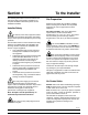
Section 1 To the Installer The following information has been included in the manual as safety and regulatory guidelines. For complete installation instructions, please see the Installation Checklist. Site Preparation Review the area where the unit will be installed before uncrating the unit. Make sure all possible hazards to the user or equipment have been addressed.
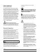
inside of the electrical box for proper power connections. Water Connections (Water Cooled Units Only) An adequate cold water supply must be provided with a hand shut-off valve. On the underside of the base pan or on the right side, two 3/8” I.P.S. water connections for inlet and outlet are provided for easy hook-up. 1/2” inside diameter water lines should be connected to the machine. (Flexible lines are recommended, if local codes permit.
Beater Rotation Refrigerant liquid sprayed onto the skin may cause serious damage to tissue. Keep eyes and skin protected. If refrigerant burns should occur, flush immediately with cold water. If burns are severe, apply ice packs and contact a physician immediately. Beater rotation must be clockwise as viewed looking into the freezing cylinder. Note: The following procedures should be performed by a trained service technician.
Section 2 To the Operator Your freezer has been carefully engineered and manufactured to give you dependable operation. When properly operated and cared for, it will produce a consistent, quality product. Like all mechanical products, cleaning and maintenance will be required. A minimum amount of care and attention is necessary if the operating procedures outlined in this manual are followed closely. compliant with the EU Directive as well as other similar legislation in effect after August 13, 2005.
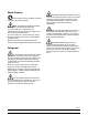
Section 3 Safety We, at Taylor Company, are concerned about the safety of the operator when he or she comes in contact with the freezer and its parts. Taylor has gone to extreme efforts to design and manufacture built-in safety features to protect both you and the service technician. As an example, warning labels have been attached to the freezer to further point out safety precautions to the operator. DO NOT use a water jet to clean or rinse the freezer.
S Supply cords used with this unit shall be oil-resistant, sheathed flexible cable not lighter than ordinary polychloroprene or other equivalent synthetic elastomer-sheathed cord (Code designation 60245 IEC 57) installed with the proper cord anchorage to relieve conductors from strain, including twisting, at the terminals and protect the insulation of the conductors from abrasion.
Section 4 Operator Parts Identification Model C709 Figure 1 ITEM DESCRIPTION PART NO. ITEM DESCRIPTION PART NO. 10 PANEL A-SIDE-RIGHT X57871 1 PANEL-SIDE-LEFT 056963-SP1 2 PAN-DRIP 11-5/8 LONG 027503 11 PANEL A.-FRONT-UPPER X59423 3 PIN-RETAINING-HOPPER CVR 043934 12 PANEL A.-FRONT-LOWER X58955 4 KIT A.-COVER-HOPPER X65368 13 STUD-NOSE CONE 055987 5 BLADE A.-AGITATOR X56591 14 SHELF-TRAY-DRIP 056076 6 TUBE A.
Model C709 Single Spout Door and Beater Assembly Figure 2 ITEM DESCRIPTION PART NO. ITEM 1 HANDLE A.-DRAW-WELDED X56246 9 2 O-RING-1/4 OD X .070W 50 015872 3 SCREW-ADJUSTMT-5/16-24 4 NUT-STUD BLACK 3.250” 5 DESCRIPTION PART NO. PIN-HANDLE-SS 055819 10 GASKET-DOOR HT 4”-DBL 048926 056332 11 BEARING-FRONT 050216 058765 12 BEATER A.-3.4 QT HELICORE X31761 NUT-STUD BLACK 2.563“ 058764 13 BLADE-SCRAPER-PLASTIC 035174 6 DOOR A.
Model C717 Figure 3 130129 Models C709 & C717 9 Operator Parts Identification
Model C717 Exploded View Parts Identification ITEM DESCRIPTION PART NO. ITEM DESCRIPTION PART NO. 1 COVER-HOPPER 053809-1 14 PANEL A.-FILTER-LOUVERED X59928 2 BLADE A.-AGITATOR X56591 15 CASTER-4” SWV 3/4-10 STEM 044106 3 ORIFICE 022465-100 16 SCREW-1/4-20 X 3/8 RHM-SS 011694 4 TUBE A.-FEED-SC-INNER-3/16 X32824-3 17 PANEL-CORNER-FRONT R. 063087 5 TUBE A.-FEED-OUTER-HT X34641 18 046437 6 O-RING-.643 OD X .
Model C717 Three Spout Door and Beater Assembly Figure 4 ITEM DESCRIPTION PART NO. ITEM 9 DESCRIPTION PIN-HANDLE-TWIN PART NO. 1 DOOR A.-3SPT*HT*LG BAF X59923-SER 059894 1a BAFFLE A.-LONG 4 IN W/RAD X50882 10 GASKET-DOOR HT 4"-DOUBLE 048926 2 HANDLE A.-DRAW-WELDED X56421-1 11 NUT-STUD BLACK 3.250 LONG 058765 3 O-RING-1/4 OD X .070W 50 015872 12 NUT-STUD BLACK 2.563 LONG 058764 4 SCREW-ADJUSTMENT-5/16-24 056332 13 BEARING-FRONT 050216 5 VALVE A.
Feed Tube Assembly Figure 5 ITEM DESCRIPTION PART NO. ITEM DESCRIPTION PART NO. 1 AIR ORIFICE 022465-100 3 O-RING - .291 ID x .080 W 018550 1a O-RING 016137 4 TUBE A.-FEED-OUTER-HT X34641 2 TUBE A.-FEED-SC-INNER (C709) X32824-2 5 O-RING- .643 OD x .077 W 018572 TUBE A.
Accessories Figure 6 ITEM DESCRIPTION PART NO. 1 PAIL-10 QT. 013163 2 TOOL-O-RING REMOVAL 048260-WHT 3 LUBRICANT-TAYLOR HI-PERF 048232 ITEM *4 **5 DESCRIPTION PART NO. SANITIZER KAY-5 25 PACKS SEE NOTE KIT A.-TUNE-UP (C709) X49463-92 KIT A.-TUNE-UP (C717) X49463-79 *Note: A sample container of sanitizer is sent with the unit. For reorders, order Kay-5 part no. 041082 (200 packs) or Stera Sheen part no. 055492 (100 2 oz. packs).
Brushes Figure 7 ITEM DESCRIPTION PART NO. ITEM DESCRIPTION PART NO.
Section 5 Important: To the Operator Figure 8 ITEM 1 2 3 4 5 6 7 8 9 10 11 DESCRIPTION POWER SWITCH LIQUID CRYSTAL DISPLAY KEYPADS MIX OUT INDICATOR STANDBY KEY MIX LOW INDICATOR SELECT KEY SERVICE MENU KEY BRUSH CLEAN COUNTER ARROW KEYS TOPPING HEATER KEY 130228 Models C709 & C717 15 Important: To the Operator
Power Switch Symbol Definitions When placed in the ON position, the power switch allows control panel operation. To better communicate in the International arena, symbols have replaced words on many of our operator switches, function, and fault indicators. Your Taylor equipment is designed with these International symbols. Fluorescent Display The fluorescent display is located on the front control panel. During normal operation the display is blank.
IMPORTANT: Make sure the level of mix in the hopper is below the mix delivery hole in the feed tube. Failure to follow this instruction may result in lower product quality when normal operation is resumed. WARNING: Do not use metal objects to press the reset button. Failure to comply may result in severe personal injury or death. To resume normal operation, press the AUTO symbol . When the unit cycles off, the product in the freezing cylinder will be at serving viscosity.
System Data Operating Screen Descriptions System data is protected separately from the rest of the data in memory. System data includes variables that change frequently such as the mode the machine is in, lockout status, serving counters, fault codes, and others. While System Data is being checked the following screen is displayed. The fluorescent display located in the center of the control panel is normally blank during the daily operation of the machine.
If Lockout Data is corrupted, all lockout history data is cleared. A “LOCKOUT CRC ERR” fault is displayed. Power Switch ON When the power switch is placed in the ON position, the control panel touch keys become operative. The fluorescent display will be either blank or indicate that the unit has been cleaned. After the memory integrity has been tested, the Safety Timeout screen will be displayed. Heat Cycle Data Heat cycle data is checked separately from the rest of the data in memory.
Use the up or down arrow symbol to move the cursor to “YES”. Touch the SEL symbol to immediately start a heat cycle. When the entire heat cycle has been completed, the HEAT symbol will no longer be illuminated. The machine will enter the STANDBY mode (STANDBY symbol illuminates). The machine can be placed in AUTO or left in STANDBY. Note: The machine must be in AUTO or STANDBY and have sufficient mix in the hopper before the machine can successfully enter the HEAT mode of operation.
Touching the SEL symbol will display the following screen. Soft Lock If a heat treatment cycle has not been initiated within the last 24 hours, a soft lock failure will occur. A soft lock allows the operator to correct the cause of the soft lock. The operator has the option of either starting another heat cycle or brush cleaning the machine. When a soft lock occurs, the machine will go into the STANDBY mode. The following message is displayed on the screen.
A soft lock can also occur any time during operation when the hopper or freezing cylinder temperature rises above 59°F (15°C), the temperature rises and remains above 45°F(7°C) for more than one hour, or the temperature rises and remains above 41°F(5°C) for more than four hours. To restore the message that identified the reason for the soft lock, turn the power switch OFF for five seconds, and then return the power switch to the ON position.
There is a two minute time-out in effect during the Manager's Menu. While in the Manager's Menu, if no activity occurs within a two minute period, the display will exit to the Main Menu. There is one exception to this time-out, and that is the Current Conditions Display. Manager Menu Options Note: The machine will continue operation in the mode it was in when the Menu was selected. However, the control keys will not be lit and are non- functional when the Manager’s Menu is displayed.
Reset the SERVINGS COUNTER by touching the SEL symbol to advance to the next screen. Touch the UP arrow symbol to move the arrow (>) to YES and touch the SEL symbol. The servings counter will reset to zero and exit back to the Manager's Menu. Enter the correct month, day, and year. Then touch the SEL symbol to advance to the DAYLIGHT SAVING TIME (DST) screen.
Pressing the UP or DOWN symbol will move the arrow to the appropriate week for the start of DST. Pressing the SEL symbol next to the appropriate week will display the following screen. Press the UP or DOWN symbol to move the arrow to the appropriate month for the end of DST. Touch the arrow symbols to increase or decrease the hour to the desired setting. Then move the cursor to the minutes position by touching the SEL symbol. Adjust the setting for minutes.
Use the arrow symbols to program the AUTO START TIME by increasing or decreasing the hour setting above the cursor. Touch the SEL symbol to advance the cursor and program the minutes setting. Touch the SEL symbol to return to the previous screen with the new time setting displayed. Touch the SEL symbol to exit the screen and return to the Menu. Fault Description The Fault Description screen will indicate if there is a fault with the freezer and where the fault occurred.
Fault History Faults Occurring Entering a Heat Treatment Cycle The FAULT HISTORY will display up to 100 faults that have occurred. The most recent fault is displayed on screen 1. The date, time, and fault description is displayed on each screen. POWER SWITCH OFF - The power switch is OFF. AUTO OR STBY OFF - The control was not in the AUTO or STANDBY mode. MIX OUT FAILURE - A Mix Out condition was present.
Faults Occurring While in AUTO Mode Heat Cycle Summary The HEAT CYCLE SUMMARY screen displays the hours since the last heat cycle, the hours since the product temperature was above 150_F (65.6_C), and the number of heat cycles completed since the last brush clean date. (L/R) HPR>41F (5C) AFTER 4 HR - The mix temperature in the hopper was above 41°F (5°C) more than four hours.
The third screen shows the right side (R) of the freezer. Listed below are variable failure code messages which could appear on line 2. HT HEAT TIME FAILURE Mix temperature did not rise above 151_F (66.1_C) in less than 90 minutes. CL HEAT = Total time for the hopper (h) and barrel (b) to reach 150.9°F (66.1°C). COOL MODE FAILURE Mix temperature in the hopper and freezing cylinder did not fall below 41_F (5_C) in less than 90 minutes for UVC3 units or 120 minutes for UVC4 units.
System Information Current Conditions The CURRENT CONDITIONS screen provides the viscosity readings for the product when the machine is running, and the hopper and the freezing cylinder temperatures for the machine. The SYSTEM INFORMATION is displayed on three separate screens. The first screen contains the control and software version installed in the machine. VISC HOPPER BARREL SOFTWARE VERSION C709 CONTROL UVC VERSION X.XX > Next 0.0 41.0 41.
Section 6 Operating Procedures The C709 machine stores mix in a hopper. It has a 3.4 quart (3.2 liter) capacity freezing cylinder with a single spout door. The C717 machine stores mix in two hoppers. It has two 3.4 quart (3.2 liter) capacity freezing cylinders with a three spout door. We begin our instructions at the point where we enter the store in the morning and find the parts disassembled and laid out to air dry from the previous night's cleaning.
Step 5 Slide the beater the remainder of the way into the freezing cylinder and over the end of the drive shaft. The beater should fit snugly, but not so tightly that the beater cannot be turned slightly to engage the drive shaft. If the beater slides in too easily with little or no resistance, there will not be enough force against the beater to hold the blades in place. Step 3 Take one of the scraper blades and slip it under the hook at the front of the beater.
Model C709 Freezer Door Assembly (Cont'd.) Step 2 Slide the three o-rings into the grooves on the draw valve and lubricate. (See Figure 17.) Figure 19 Step 5 Insert the baffle rod through the beater in the freezing cylinder. With the door seated on the freezer studs, install the handscrews, with the longer ones on top. Tighten equally in a criss-cross pattern to insure the door is snug. (See Figure 20.) Figure 17 Step 3 Lightly lubricate the inside of the top of the freezer door valve cavity.
Model C709 Freezer Door Assembly (Cont'd.) Model C717 Freezer Door Assembly Note: The C709 features an adjustable draw handle to provide portion control, giving a better consistent quality to your product and controlling costs. Step 1 Place the door gaskets into the grooves on the back of the freezer door. The draw handle should be adjusted to provide a flow rate of 5 to 7-1/2 oz. (142 g. to 213 g.) of product by weight per 10 seconds. To INCREASE the flow rate, turn the adjustment screw CLOCKWISE.
Step 3 Insert the baffle rods through the beaters in the freezing cylinders. With the door seated on the freezer studs, install the handscrews, with the longer ones on top. Tighten equally in a criss-cross pattern to insure the door is snug. Step 5 Lubricate the inside of the freezer door spouts, top and bottom. Figure 28 Step 6 Insert the draw valves from the bottom until the slot in each draw valve comes into view. Figure 26 Step 4 Slide the three o-rings into the grooves of each standard draw valve.
Model C717 Freezer Door Assembly (Cont'd.) Step 8 Slide the pivot pin through the draw handles as the handles are inserted into the draw valves. Step 11 Install the front drip tray and splash shield under the door spouts. (See Figure 32.) Figure 30 Note: This freezer features adjustable draw handles to provide portion control, giving a better consistent quality to your product and controlling costs. The draw handles should be adjusted to provide a flow rate of 5 to 7-1/2 oz. (142 g. to 213 g.
Step 2 Slide the two o-rings into the grooves of the outer feed tube. Step 4 Lay the inner feed tube, the outer feed tube, and the agitator in the bottom of the mix hopper for sanitizing. Figure 36 Repeat Steps 1 through 4 for the other side of the C717. Figure 34 Sanitizing Step 1 Prepare an approved 100 PPM sanitizing solution (examples: 2- 1/2 gal. [9.5 liters] of Kay- 5R or 2 gal. [7.6 liters] of Stera- SheenR). USE WARM WATER AND FOLLOW THE MANUFACTURER’S SPECIFICATIONS.
Step 3 While the solution is flowing into the freezing cylinder, take particular care to brush-clean the mix level sensing probe on the bottom of the hopper, the mix hopper, the mix inlet hole, and the feed tubes. Step 8 Lubricate the o-rings on the inner and outer feed tubes. DO NOT lubricate the o-ring on the air orifice. Place the inner feed tube inside the outer feed tube. Step 4 Place the power switch in the ON position.
Step 10 Stand the assembled feed tube in the corner of the mix hopper and place the agitator on the agitator housing. Figure 42 Figure 41 The pin on the inner feed tube should be turned and positioned at the bottom of the notch in the outer feed tube. This will align the holes in the feed tubes and allow mix and air to enter the freezing cylinder. Step 11 Return to the freezer with a small amount of sanitizing solution.
Step 4 Prepare a small amount of an approved 100 PPM cleaning/sanitizing solution (examples: Kay-5® or Stera-Sheen®). USE WARM WATER AND FOLLOW THE MANUFACTURER'S SPECIFICATIONS. Brush clean the parts. Daily Closing Procedures This procedure must be performed once daily! Step 5 Place the front drip tray, splash shield, and air orifice(s) on a clean, dry surface to air-dry overnight or until the heating cycle is complete.
Step 9 Replace the hopper cover(s) and install the drip pans. A failure message will appear on the fluorescent display to inform the operator that the machine did not successfully complete the heat treatment cycle. The product may not be safe to serve. The freezer will be locked out (softlock) of the AUTO mode. The operator will be given the option of selecting the Step 10 Return to the freezer with a small amount of cleaning solution.
Step 3 Return to the freezer with a small amount of sanitizing solution. Dip the door spout brush into the sanitizing solution and brush clean the door spout(s) and bottom of the draw valve(s). Step 6 Lift the hopper cover(s). Turn the inner feed tube of each assembled feed tube so the pin rests at the bottom of the notch of the outer feed tube. Install the air orifice(s).
Draining Product From The Freezing Cylinder Rinsing Step 1 Pour two gallons (7.6 liters) of cool, clean water into the mix hopper. With the white hopper brush, scrub the mix hopper, mix level sensing probes and the outside of the agitator drive shaft housing. Using the double ended brush, brush clean the mix inlet hole. Step 1 Press the AUTO symbol , cancelling compressor and beater motor operation. Step 2 Remove the hopper cover, the agitator paddle, and the assembled feed tube.
Step 3 Open the draw valve on the freezer door. Drain all the rinse water from the door spout, close the draw valve and touch the WASH symbol, the Wash mode. / Disassembly Note: Failure to remove the parts specified below for brush cleaning and lubrication will result in damage to the machine. These parts must be removed within the maximum number of days allowed between brush clean cycles or the machine will hard lock and will not operate.
Step 5 Return to the freezer with a small amount of cleaning solution. Using the black brush, clean the rear shell bearing at the back of the freezing cylinder. Brush Cleaning Step 1 Prepare an approved 100 PPM cleaning solution (examples: 2-1/2 gal. [9.5 liters] of Kay-5R or 2 gal. [7.6 liters] of Stera-SheenR). USE WARM WATER AND FOLLOW THE MANUFACTURER'S SPECIFICATIONS. Make sure all brushes provided with the freezer are available for brush cleaning. Step 2 Remove all o-rings.
Section 7 Important: Operator Checklist During Brush Cleaning and Sanitizing Regular Maintenance Checks j 1. Replace scraper blades that are nicked or damaged. Before installing the beater assembly, be certain that scraper blades are properly attached to the helix. ALWAYS FOLLOW LOCAL HEALTH CODES. Cleaning and sanitizing schedules are governed by your Federal, State or local regulatory agencies and must be followed accordingly. j 2.
j 7. If your machine is equipped with an auxiliary refrigeration system, check the auxiliary condenser for accumulation of dirt and lint. Dirty condensers will reduce the refrigeration capacity of the mix hopper. Condensers must be cleaned monthly with a soft brush. Never use screwdrivers or other metal probes to clean between the fins.
Section 8 PROBLEM 1. Soft lock message appears on display. 2. Hard lock message appears on display. Troubleshooting Guide PROBABLE CAUSE REMEDY PAGE REF. a. More than 24 hours since the last HEAT cycle. a. The freezer must go through a HEAT cycle every 24 hours. The freezer must now be disassembled and brush cleaned or placed in a heat cycle. 21 b. The power switch is in the OFF position. b. The power switch must be in the ON position.
PROBLEM 3. No product is being dispensed. 4. The product is too soft. Models C709 & C717 PROBABLE CAUSE REMEDY PAGE REF. a. Low on mix. The MIX OUT light is on. a. Add mix to the mix hopper. Return to AUTO mode. 39 b. The power switch is in the OFF position. b. Place the power switch to ON and select AUTO. 38 c. The circuit breaker is off or the fuse is blown. c. Turn the breaker on, or replace the fuse. - - - d. Beater motor is out on reset, BEATER OVERLOAD message displayed. d.
PROBLEM REMEDY PAGE REF. a. Freezing cylinder not primed correctly. a. Drain the freezing cylinder and reprime the machine. 39 b. The viscosity control is set too cold. b. Call an authorized service technician. --- c. Freeze-up in mix inlet hole. c. Call an authorized service technician. --- a. Hopper cover is not in position. a. Clean and sanitize hopper cover and place in position. 39 b. The agitator is not installed. b. Clean and sanitize the agitator and install. 40 c.
PROBLEM PROBABLE CAUSE 12. The drive shaft is stuck in the drive coupling. a. Mix and lubricant collected in drive coupling. a. Brush clean the rear shell bearing area regularly. 45 b. Rounded corners of drive shaft, drive coupling, or both. b. Call an authorized service technician. --- c. Gear box is out of alignment. c. Call an authorized service technician. --- a. Missing or worn front bearing and scraper blades. a. Install or replace the front bearing and scraper blades. 32 b.
Section 9 PART DESCRIPTION Parts Replacement Schedule EVERY 3 MONTHS EVERY 6 MONTHS ANNUALLY White Bristle Brush, 3” x 7” Inspect & Replace if Necessary Minimum White Bristle Brush, 1” x 2” Inspect & Replace if Necessary Minimum Black Bristle Brush, 1” x 2” Inspect & Replace if Necessary Minimum Double-Ended Brush Inspect & Replace if Necessary Minimum Yellow Bristle Brush Inspect & Replace if Necessary Minimum Scraper Blades X Drive Shaft Seal X Freezer Door Gasket X Front Bearing
Section 10 Limited Warranty on Equipment TAYLOR COMPANY LIMITED WARRANTY ON FREEZERS Taylor Company, a division of Carrier Commercial Refrigeration, Inc. (“Taylor”) is pleased to provide this limited warranty on new Taylor-branded freezer equipment available from Taylor to the market generally (the “Product”) to the original purchaser only. LIMITED WARRANTY Taylor warrants the Product against failure due to defect in materials or workmanship under normal use and service as follows.
3. Replacement of wear items designated as Class “000” parts in the Taylor Operator’s Manual. 4. External hoses, electrical power supplies, and machine grounding. 5. Parts not supplied or designated by Taylor, or damages resulting from their use. 6. Return trips or waiting time required because a service technician is prevented from beginning warranty service work promptly upon arrival. 7.
Section 11 Limited Warranty on Parts TAYLOR COMPANY LIMITED WARRANTY ON TAYLOR GENUINE PARTS Taylor Company, a division of Carrier Commercial Refrigeration, Inc. (“Taylor”) is pleased to provide this limited warranty on new Taylor genuine replacement components and parts available from Taylor to the market generally (the “Parts”) to the original purchaser only. LIMITED WARRANTY Taylor warrants the Parts against failure due to defect in materials or workmanship under normal use and service as follows.
LIMITED WARRANTY EXCEPTIONS This limited warranty does not cover: 1. Labor or other costs incurred for diagnosing, repairing, removing, installing, shipping, servicing or handling of defective Parts, replacement Parts, or new Parts. 2. Normal maintenance, cleaning and lubrication as outlined in the Taylor Operator’s Manual, including cleaning of condensers or carbon and grease buildup. 3.
LIMITATION OF WARRANTY THIS LIMITED WARRANTY IS EXCLUSIVE AND IS IN LIEU OF ALL OTHER WARRANTIES, CONDITIONS AND/OR REMEDIES UNDER THE LAW, INCLUDING ANY IMPLIED WARRANTIES OR CONDITIONS OF MERCHANTABILITY OR FITNESS FOR A PARTICULAR PURPOSE. THE ORIGINAL OWNER'S SOLE REMEDY WITH RESPECT TO ANY PRODUCTS SHALL BE REPAIR OR REPLACEMENT OF DEFECTIVE PARTS UNDER THE TERMS OF THIS LIMITED WARRANTY.
LINE BLK HOPPER GROUND BLK BLK BLK L1 L1 LINE L2 L2 WHT WHT GRN/YEL LOAD EMI FILTER 240V NOT CONNECTED 16V WHT CLR (+5v) J16 BLK (GRD) J15 J4 J2 J8 J13 J9 J1 J3 USER INTERFACE BOARD RIBBON CABLE J7 J11 J1 - 8 LEDS - LCD SCREEN - 9 KEYS - BEEPER RIBBON CABLE GRD SV CABLE BRN/WHT WHT WHT BLK GRN/YEL RED L1 L2 (SEE FIG.
BLK HOPPER GROUND L2 L2 WHT WHT J4 J2 J13 J9 J1 J3 USER INTERFACE BOARD RIBBON CABLE J7 J8 - 8 LEDS - LCD SCREEN - 9 KEYS - BEEPER RIBBON CABLE GRD RED BRN/WHT BLK L1 L2 L3 BRN/WHT 1 2 8 7 208 6 8 7 BLK/BLU 6 COM YEL/BLK 0 BLUE 24 VAC 2 HOPPER HOT GAS SOLENOID GRA EXTERNAL EQUIPOTENTIAL GROUND GROUND WHT BARREL HOT GAS SOLENOID BLU/WHT BLK BLK BLU/WHT BLU/WHT WHT BLU/WHT 3 9 HOPPER HOT GAS SOLENOID RELAY BLK BRN/WHT BARREL HOT GAS SOLENOID RELAY BRN/WHT BLK
BLK GRN/YEL BLK BLK L1 L1 LINE L2 L2 WHT GRN/YEL 240V LOAD EMI FILTER NOT CONNECTED WHT WHT J4 BLK (GRD) CLR (+5V) J16 J15 BOARD J7 J8 J13 J9 - 8 LEDS - LCD SCREEN - 9 KEYS - BEEPER RIBBON CABLE J1 USER J3 INTERFACE J2 J11 J1 RIBBON CABLE GRD BRN/WHT BLK BRN WHT GRN/YEL WHT TERMINAL BLOCK GRA/BLK GRA L1 N GRN/YEL BLU/WHT BARREL HOT GAS SOLENOID YEL 1 BRN/WHT 7 240 2 COM 0 BLU BLK/RED 24 VAC BLK 6 WHT WHT/ORN BLK 8 3 7 14 8 4 5 1 BEATER INTERL
BLK BLK LINE L2 L2 WHT WHT GRN/YEL LOAD 240V ORN BLK L1 L1 EMI FILTER WHT J15 J4 BLK (GRD) CLR (+5V) J16 J12 J1 J3 J2 J8 J13 J9 USER INTERFACE BOARD J7 J11 - 8 LEDS - LCD SCREEN - 9 KEYS - BEEPER J1 RIBBON CABLE GRD +5v RED BRN/WHT BRN WHT GRN/YEL WHT TERMINAL BLOCK GRA/BLK GRA L1 L2 L3 N WHT ELECTRICAL ENCLOSURE GRN/YEL BLU/WHT YEL 240 BRN/WHT 7 COM 2 6 0 BLK BLU BLK/RED 24 VAC BLK WHT WHT/ORN 8 3 7 13 12 9 BLK 14 8 4 5 1 BEATER INTERLOC
SE WHT BLUE M GE/RBC/MARATHON BEATER MOTOR WIRING NOTE: FOR CCWLE - BLUE INTERNAL ON #1,YELLOW INTERNAL ON #2 RED BEATER MOTOR CONTACTOR J12 OR PURPLE INTERNAL BLACK T1 L1 5 BLU/WHT BLUE T1 OR BLUE INTERNAL T8 OR RED INTERNAL BLUE 4 1 BLUE J9 OR BLACK INTERNAL AGITATOR MOTOR DETAIL A CP CP T3 L3 2 USE T3 AND L3 WHEN CP CONTACTS ARE NOT AVAILABLE BLACK T2 L2 T4 OR YELLOW INTERNAL EXTERNAL EQUIPOTENTIAL GROUND GROUND A.O.
EXTERNAL EQUIPOTENTIAL GROUND GROUND L3 L1 L2 THERMOSTA 190 F OPEN 140 F CLOSE BLK/BLU (+5v) CLR ) (GRD GRN WHT CABLE RED GRN WHT RED BLK J13 J8 J15 J12 1 23 J9 J7 J2 4 56 WHT GRD GRA BARREL HOT GAS SOLENOID UNIVERSAL CONTROL PCB A. J1 RED BLK WHT WHT WHT ORN WHT/ORN BLK BLK 8 14 AGITATOR MOTOR DETAIL BLACK BEATER MOTOR INTERLOCK N.O.
SE WHT BLUE M GE/RBC/MARATHON BEATER MOTOR WIRING NOTE: FOR CCWLE - BLUE INTERNAL ON #1,YELLOW INTERNAL ON #2 RED BEATER MOTOR CONTACTOR J12 OR PURPLE INTERNAL BLACK L1 T1 5 BLU/WHT BLUE T1 OR BLUE INTERNAL T8 OR RED INTERNAL BLUE 4 1 BLUE J9 OR BLACK INTERNAL AGITATOR MOTOR DETAIL CP CP T3 L3 2 A USE T3 AND L3 WHEN CP CONTACTS ARE NOT AVAILABLE BLACK T2 L2 T4 OR YELLOW INTERNAL EQUIPOTENTIAL EXTERNAL GROUND GROUND A.O.
EQUIPOTENTIAL GROUND EXTERNAL GROUND BLK BLK/RED GRN/YEL GRN/YEL WHT BEATER MOTOR LINE MUST PASS TWICE THRU THE SENSOR CORE.