Models H71/H84 Heat Treatment Soft Serve Freezers Operating Instructions 048886- M 1/21/02
Complete this page for quick reference when service is required: Taylor Distributor: Address: Phone: Service: Parts: Date of Installation: Information found on the data label: Model Number: Serial Number: Electrical Specs: Voltage Cycle Phase Maximum Fuse Size: A Minimum Wire Ampacity: A E January, 2002 Taylor All rights reserved.
Table of Contents Section 1 To the Installer . . . . . . . . . . . . . . . . . . . . . . . . . . . . . . . . . . . . . . . . . . . . Water Connections (Water Cooled Units Only) . . . . . . . . . . . . . . . . . . . . . . . . . . . . Air Cooled Units . . . . . . . . . . . . . . . . . . . . . . . . . . . . . . . . . . . . . . . . . . . . . . . . . . . . . . . Electrical Connections . . . . . . . . . . . . . . . . . . . . . . . . . . . . . . . . . . . . . . . . . . . . . . . . . Section 2 To the Operator . . .
Table of Contents -- Page 2 Section 7 Important: Operator Checklist . . . . . . . . . . . . . . . . . . . . . . . . . . . . . . During Cleaning and Sanitizing . . . . . . . . . . . . . . . . . . . . . . . . . . . . . . . . . . . . . . . . . Troubleshooting Bacterial Count: . . . . . . . . . . . . . . . . . . . . . . . . . . . . . . . . . . . . . . . . Regular Maintenance Checks: . . . . . . . . . . . . . . . . . . . . . . . . . . . . . . . . . . . . . . . . . . Winter Storage . . . . . . . . . . . . . . . .
Section 1 To the Installer In the United States, this equipment is intended to be installed in accordance with the National Electrical Code (NEC), ANSI/NFPA 70--1987. The purpose of the NEC code is the practical safeguarding of persons and property from hazards arising from the use of electricity. This code contains provisions considered necessary for safety.
Section 2 To the Operator Compressor Warranty Disclaimer The freezer you have purchased has been carefully engineered and manufactured to give you dependable operation. The Taylor Models H71 and H84, freezers, when properly operated and cared for, will produce a consistent quality product. Like all mechanical products, this machine will require cleaning and maintenance. A minimum amount of care and attention is necessary if the operating procedures outlined in this manual are followed closely.
Section 3 Safety We at Taylor Company are concerned about the safety of the operator when he or she comes in contact with the freezer and its parts. Taylor has gone to extreme efforts to design and manufacture built-in safety features to protect both you and the service technician. As an example, warning labels have been attached to the freezer to further point out safety precautions to the operator.
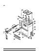
Section 4 Operator Parts Identification H71 Operator Parts Identification 4 Models H71 & H84
H71 Parts Identification ITEM DESCRIPTION PART NO. ITEM DESCRIPTION PART NO. 1 COVER-HOPPER 053809 12 TRAY-DRIP 14.8 046275 2 PANEL A.-LOWER SIDE X39075-SER 13 SHIELD-SPLASH-WIRE 046177 3 AGITATOR A. *HT*20 QT. X44797 14 PANEL A.
H84 Operator Parts Identification 6 Models H71 & H84
H84 Parts Identification ITEM DESCRIPTION PART NO. ITEM DESCRIPTION PART NO. 1 COVER-HOPPER 053809 12 SHIELD-SPLASH-WIRE 046170 2 AGITATOR A. *HT*20 QT. X44797 13 TRAY-DRIP 22-13/16 X 5-1/8 046171 3 PANEL-UPPER SIDE LEFT 028822 14 PANEL A.-FRONT X46167 4 PAN-DRIP 17-1/4”LONG 027504 15 CASTER-SWV 5/8 STEM 4IN 018794 5 STUD-NOSE CONE 022822 16 LOUVER-SIDE-RIGHT 017471 6 PANEL A.
Beater Door Assembly -- H71 ITEM DESCRIPTION PART NO. ITEM DESCRIPTION PART NO. 1 DOOR A.-1 SPOUT X51531-9 6 DESIGN CAP 014218 2 VALVE A.-DRAW X33582 7 DRIVE SHAFT SEAL 032560 3 O-RING (DRAW VALVE) 014402 8 PIVOT PIN X22820 4 BEATER ASSEMBLY X31761 9 O-RING (PIVOT PIN) 016272 5 HANDLE A.-DRAW-ADJ. X44212 10 DRIVE SHAFT 032564 5a DRAW HANDLE 044197 11 FRONT BEARING 050216 5b SCREW-ADJUSTMENT 055092 12 SCRAPER BLADE 035174 5c O-RING (SCREW ADJ.
Beater Door Assembly -- H84 ITEM DESCRIPTION PART NO. ITEM DESCRIPTION PART NO. 1 SEAL-DRIVE SHAFT 032560 9c O-RING-1/4 OD X .070W 50 015872 2 SHAFT-BEATER 032564 9d NUT-JAM 5/16-24 029639-BLK 3 BLADE-SCRAPER-PLASTIC 035174 10 O-RING-5/16 OD X .070W 016272 4 BEATER A.-3.4QT-HELICORE X31761 11 ROD A.-PIVOT X20683 5 SEAL-DRAW VALVE 034698 12 NUT-STUD LONG 034382 6 BEARING-FRONT 050216 13 VALVE A.
Feed Tube Assembly 2 1a 1 4 3 5 ITEM DESCRIPTION PART NO. ITEM DESCRIPTION PART NO.
Accessories 3 048260 8 1 2 4 7 5 R LU BE HP 6 ITEM DESCRIPTION 1 BRUSH-MIX PUMP BODY-3 X 7 2 BRUSH-END-DOOR-SPOUT 3 4 PART NO. ITEM DESCRIPTION PART NO. 023316 5 BRUSH-REAR BRG 1IN.D X 2IN 013071 039719 6 BRUSH-DRAW VALVE 1”ODX2” 013073 KIT A.-TUNE UP-H71 X49463-10 7 LUBRICANT-TAYLOR HI PERF. 048232 KIT A.-TUNE UP-H84 X49463-3 8 PAIL-MIX 10 QT.
Section 5 Important: To the Operator H71 H84 ITEM 1 2 3 4 DESCRIPTION ITEM POWER SWITCH (TOGGLE) LCD DISPLAY KEYPADS MIX LOW INDICATOR LIGHT Important: To the Operator 5 6 7 12 DESCRIPTION MIX OUT INDICATOR LIGHT HEAT MODE INDICATOR LIGHT CLEAN MANUALLY INDICATOR LIGHT Models H71 & H84
Symbol Definitions Indicator Lights MIX LOW - When the MIX LOW light begins to flash, it indicates the mix hopper has a low supply of mix and should be refilled as soon as possible. On double head units, the word “LOW” will also display on the LCD indicator next to the word “MIX”. To better communicate in the International arena, the words on many of our operator switches and buttons have symbols to indicate their functions. Your Taylor equipment is designed with these International symbols.
Adjustable Draw Handle This screen will be displayed, with the alarm on, for 60 seconds or until any key is pressed. After the safety timeout has been completed, and the power switch is OFF, one of the following screens is displayed. This unit features an adjustable draw handle to provide the best portion control, giving a better, consistent quality to your product and controlling costs. The draw handle should be adjusted to provide a flow rate of 5 to 7-1/2 oz. of product by weight per 10 seconds.
The following displays pertain to the HEAT cycle: While in the heating phase, you will see this display. It shows the present temperature of the hopper. H84 Screen: OFF OK 40.0F BRUSH CLEAN ON: :MODE: :MIX: HOPPER MM/DD OFF OK 40.0F H71 Screen: MODE: HEAT PHASE: HEAT HOPPER TEMP: 140.0 F BRUSH CLEAN ON: MM/DD The next display indicates the freezer is operating in two different modes. The following information is given: H84 Screen: HEAT HEAT 140.
The final phase of the heat treatment cycle is the cooling phase. Now the freezer must cool the mix below 41_F (5_C). If the product fails to cool in two hours, the freezer will lock out. Hard Lock: There are two causes for a hard lock: 1. Fourteen days have elapsed since the last brush cleaning. The following screen will be displayed. This example illustrates that the temperature is being lowered, but has not yet reached the set point.
If the temperature of the product has not fallen below 41_F (5_C) by the end of the COOL cycle, the following screen will appear. H84 Screen: OFF OK 41.0F FREEZER LOCKED :MODE: :MIX: HOPPER OFF OK 41.0F PRODUCT OVER TEMP FREEZER LOCKED PRESS SEL KEY Soft Lock: If a heat treatment cycle has not been initiated within the last 24 hours, all four LED’s on the front of the machine will light and a message will appear on the LCD. Line 3 of the LCD will indicate the reason the message appears.
Operator Menu The OPERATOR MENU is used to enter the operator function displays. To access the OPERATOR MENU, simply press the MENU key. The cursor will flash over the letter “A” indicating that this is screen “A”. To select a different screen, use the arrow keys and move the cursor to the desired screen selection and press the SEL key. OPERATOR MENU ABCDEFGHIJ EXIT FROM MENU <- - - - - -> 7. GLYCOL THERM BAD: Place the power switch in the OFF position. Call a service technician. 8.
Screen “C” is SET CLOCK. This screen will display the current date and time. The date and time may be changed only after the freezer has been manually brush cleaned, but before it has been placed in the AUTO mode. Move the cursor under the number you wish to change. Press the plus key to increase the number; press the minus key to decrease the number. When the desired time and date appears, press the SEL key once to return to the OPERATOR MENU.
The SERVINGS COUNTER screen indicates the number of times the draw switch has closed (number of draws) since the last brush cleaning or since the last serving counter reset. A maximum of 32,767 draws can be recorded; an additional draw will cause the counter to restart at zero. Pressing the MENU key/SEL will return the display to the Operator Menu. Listed below are the variable messages which could appear: HT CL TT Failure in the heating phase. Failure in the cooling phase.
Pressing the left arrow key on any HEAT CYCLE DATA screen will cause the extended data screen to be displayed. This screen shows the hopper, barrel, and glycol temperatures, and the amount of time the freezer spent in the phases of the heat cycle when the heat cycle completed, or was terminated. H71 Screen: HOPPER 151.0 BARREL 134.5 Screen “I” is the SERVICE MENU. This screen can only be accessed by a service technician. Screen “J” is the STANDBY MODE.
Section 6 Operating Procedures The “Operator Parts Identification” section in this manual has been included to identify components referenced in these instructions. If this is the first time you have read these procedures, please turn to the “Operator Parts Identification” section, and familiarize yourself with these components before proceeding with the instructions. Step 1 Lubricate the groove and shaft portion that come in contact with the bearing on the beater drive shaft.
Holding the beater securely, slide the beater into the freezing cylinder about one-third of the way in. Looking into the freezing cylinder, align the hole at the rear of the beater with the flats on the end of the drive shaft. Install the drive shaft. Insert the drive shaft into the freezing cylinder, hex end first, and into the rear shell bearing until the seal fits securely over the rear shell bearing. Be certain the drive shaft fits into the drive coupling without binding.
Lubricate the inside of the freezer door spout(s), top and bottom, and insert the draw valve(s) from the bottom until the slot in the draw valve(s) comes into view. Step 4 Install the freezer door. Insert the baffle rod(s) through the opening in the beater assembly(ies) and seat the door flush with the freezing cylinder(s). With the door seated on the freezer studs, install the handscrews. Tighten equally in a criss-cross pattern to insure the door is snug. Figure 9 Step 6 Install the draw handle(s).
Note: The Model H84 has three draw handles. Slide the fork of the draw handle in the slot of the draw valve, starting from right to left. Slide the pivot pin through each draw handle as you insert them into the draw valves. Step 9 Slide the three o-rings into the grooves of the inner air tube. Step 7 Install the front drip tray and the splash shield under the door spout(s). Figure 14 Slide the two o-rings into the grooves of the outer air tube.
Step 10 Lay the inner air tube, outer air tube, and agitator in the bottom of the mix hopper for sanitizing. Step 4 Press the WASH key and allow the sanitizing solution in the freezing cylinder to agitate for five minutes. 12151 Figure 18 Figure 17 Step 5 With a pail beneath the door spout(s), open and close the draw valve six times. Open the draw valve and draw off the remaining sanitizing solution. Repeat Steps 9 and 10 for the other side of the freezer on the Model H84.
Step 7 Lubricate the o-rings on the inner and outer air tubes. DO NOT lubricate the o-ring on the air orifice. Place the inner air tube inside the outer air tube. Step 9 Stand the assembled air tube in the corner of the mix hopper and place the agitator on the agitator housing. 12153 Figure 20 Figure 22 Step 8 Install the air orifice into the hole in the top of the inner air tube. Make sure the hole in the air orifice is clean and not blocked.
Priming The pin on the inner air tube should be turned and positioned at the bottom of the notch in the outer air tube. This will align the holes in the air tubes and allow mix and air to enter the freezing cylinder. Note: Evaluate the condition of LED’s (lights) and screen messages before performing priming procedures. If all 4 LED’s are flashing, the unit is locked. 12155 Step 1 With a mix pail beneath the door spout, open the draw valve. Pour two gallons (7.
Note: Use only FRESH mix when priming the freezer. Note: Pressing the left arrow button will stop the agitator(s) motion for ten seconds. Repeat Steps 1 through 4 for the other side of the freezer on the Model H84. Note: These units feature adjustable draw handles to provide the best portion control, giving a better, consistent quality to your product, and controlling costs. The draw handles can be adjusted for different flow rates. See page 14 for more information on adjusting these handles.
Note: Once the heating cycle has started it cannot be interrupted. The heating cycle will take a maximum of 4 hours to complete with full hoppers. Step 6 Install the air tube assembly(ies). Lift and turn the inner air tube of the assembled air tubes so the pin rests on top of the outer air tube. This will close the hole in the assembled air tubes, preventing mix in the hopper from entering the freezing cylinder during the heating and standby process.
Manual Brush Cleaning Step 1 When the heating cycle is complete, the normal display will appear, showing the machine in the STANDBY mode. Prepare a small amount of an approved 100 PPM sanitizing solution (example: Kay-5r). USE WARM WATER AND FOLLOW THE MANUFACTURER’S SPECIFICATIONS. THIS PROCEDURE MUST BE DONE EVERY 14 DAYS! Sanitize the design caps, air orifices, front drip tray, and the splash shield in this solution. ALWAYS FOLLOW LOCAL HEALTH CODES.
Rinsing Step 8 Place an empty pail beneath the door spout. Step 1 Pour two gallons (7.6 liters) of cool, clean water into the mix hopper. With the brushes provided, scrub the mix hopper, mix level sensing probes, the outside of the agitator housing, and the mix inlet hole. Step 9 Open the draw valve on the freezer door and draw off all the solution. Step 10 Once the cleaner stops flowing from the door spout, close the draw valve and press the WASH key cancelling the wash cycle.
Step 3 From the freezer door, remove the following: S gaskets(s) S front bearing(s) S pivot pin S draw handle(s) S design cap(s) S draw valve(s) Remove all o-rings. Step 6 Remove the rear drip pan from the front panel and take to the sink for cleaning. Note: If the drip pan is filled with an excessive amount of mix, refer to the Troubleshooting Guide. Step 7 Thoroughly brush clean all disassembled parts in the cleaning solution, making sure all lubricant and mix film is removed.
Section 7 Important: Operator Checklist During Cleaning and Sanitizing j 7. Discard remaining mix from freezer during “Closing Procedures”. ALWAYS FOLLOW LOCAL HEALTH CODES. Regular Maintenance Checks: Cleaning and sanitizing schedules are governed by your State or local regulatory agencies and must be followed accordingly. The following check points should be stressed during the cleaning and sanitizing operations. j 1. Replace scraper blades that are nicked or damaged.
Winter Storage If the place of business is to be closed during the winter months, it is important to protect the freezer by following certain precautions, particularly if the building is to be left unheated and subject to freezing conditions. Your local Taylor Distributor can perform this service for you. Wrap detachable parts of the freezer such as beater, blades, drive shaft, and freezer door, and place in a protected dry place.
Section 8 Troubleshooting Guide PROBLEM 1. All four LED’s are flashing. PROBABLE CAUSE a. The freezer is locked. Troubleshooting Guide PAGE REF. a. See soft lock and hard lock information. 16 -- 17 b. Freezer must go through a Heat Treatment Cycle every 24 hours. Freezer must now be disassembled and brush cleaned or placed in a heat cycle. 17 c. Power switch is in the OFF position. c. Power switch must be in the ON position.
PROBLEM 4. Drive shaft stuck in gear box coupling. 5. No product being dispensed with draw valve open and machine in AUTO mode. 6. Product too stiff. 7. Product too soft. PROBABLE CAUSE REMEDY PAGE REF. a. Rounded corners of drive shaft, coupling, or both. a. Call service technician to correct cause and replace the necessary components. Do not lubricate end of drive shaft. ---- b. Mix and lubricant collected in drive coupling. b. Brush clean rear shell bearing area regularly. 33 a.
PROBLEM 11. Excessive mix leakage into rear drip pan. 12. Excessive mix leakage from the door spout. 13. No freezer operation after placing unit in AUTO. 14. Product not feeding into freezing cylinder. Troubleshooting Guide PROBABLE CAUSE REMEDY PAGE REF. a. Worn or missing seal on drive shaft. a. Replace regularly. 39 b. Inadequate lubrication of drive shaft. b. Follow lubrication procedures in “Assembly”. 22 c. Worn rear shell bearing. c.
Section 9 PART DESCRIPTION Parts Replacement Schedule EVERY 3 MONTHS EVERY 6 MONTHS ANNUALLY Minimum QUANTITIES TO BE REPLACED H71 H84 2 4 Scraper Blade X Drive Shaft Seal X 1 2 Freezer Door Gasket X 1 2 Front Bearing X 1 2 Draw Valve O-Ring X 3 7 Pivot Pin O-Ring X 1 1 Design Cap X 1 3 Inner Air Tube O-Ring X 3 6 Outer Air Tube O-Ring X 2 4 Air Orifice O-Ring X 1 2 Center Draw Valve Seal (Model H84 only) X 1 White Bristle Brush, 3” x 7” Inspect & Replace i
ADAPTOR A.-CASTER ACCUMULATOR-GLYCOL (OLD STYLE) CAP-RADIATOR (OLD STYLE) AGITATOR A. *HT*20 QT HOPPER BEARING-FRONT BEARING-REAR SHELL *NICK.PLATE +GUIDE-DRIP SEAL +NUT-BRASS BEARING +WASHER-BEARING LOCK BEATER A.-3.4QT-HELICORE +BLADE-SCRAPER-PLASTIC BELT-AX35 BELT-AX31 BELT-RD 3/16W X 4.70 ID BELT-RD 3/16 W X 4.01 ID BELT-RD 3/16 W X 9.12 ID BLOCK-TERMINAL-2 POLE BLOCK-TERMINAL-5 POLE BLOCK-TERMINAL-PLUG 10P .2 SIP BLOCK-TERMINAL-PLUG 7P .2 SIP BLOCK-TERMINAL-PLUG 8P .2 SIP BLOWER A. HOUSING A.
+ Available Separately Models H71 & H84 41 Parts List CABLE-RIBBON-10C-56”L-DIL/DILR CABLE-RIBBON-14C-14”L SIP/SIPR CABLE-RIBBON-20C-63”L-DIL/DILR CABLE-RIBBON-20C-72”L-DIL/DIL CABLE-RIBBON-20C-74”L-DIL/DILR CABLE-RIBBON-20C-9 DIL/DIL CABLE-RIBBON-50C-56”L-DIL/DIL CABLE-RIBBON-50C-65 DIL/DIL CABLE-2 COND -#22 SHIELDED CABLE-2 COND -#22 SHIELDED CAP-DESIGN-1.010”ID-6 POINT CAPACITOR-RUN- .
+ Available Separately Parts List 42 Models H71 & H84 +PIN-RETAINING-HOPPER COVER +RETAINER-HOPPER COVER +SCREW-8-32 X 1/2 OVAL HD-SS DECAL-DAILY CLEANING-HT SS/YOG DECAL-DEC-TAYLOR-H71 DECAL-DEC-TAYLOR-H84 (NEW) DECAL-DEC-TAYLOR-H84 (OLD) DECAL-MANUAL CLEANING DECAL-TROUBLESHOOTING DEFLECTOR-BLOWER EXHAUST DEFLECTOR-BLOWER EXHAUST DIAGRAM-WIRING DIAGRAM-WIRING *PH71* DIAGRAM-WIRING DIAGRAM-WIRING *P/H84* DISPLAY-LIQUID CRYSTAL +LENS-DISPLAY +SCREW 2-56 X 1/2 FHM +NUT-HEX DOOR A.-HT-1 SPT DOOR A.
+ Available Separately Models H71 & H84 43 Parts List + DECAL-FREEZER DOOR +GASKET-DOOR-HT +HANDLE A.-DRAW-ADJ O-RING-1/4 OD X .070W 50 DURO SCREW-ADJUSTMENT HANDLE-ADJUSTABLE +NUT -5/16-24 18-8 SS JAM +ROD A.-PIVOT +O-RING-5/16 OD X .070W +VALVE A.-DRAW CENTER *754 HT* +SEAL-DRAW VALVE +VALVE A.-DRAW*SELF CLEANING* +O-RING-7/8 OD X .103W DRYER-FILTER HP62-3/8 X 1/4 S DRYER-FILTER 3/8 X 1/4 SOLDER FILTER-CORCOM 6EH1 FILTER-INLINE-GLYCOL-40 MICRON +ARMAFLEX-BOOT 1-3/8 ID X 3/8W FLUID A.
+ Available Separately Parts List 44 Models H71 & H84 050216 X51532-11 048926 034383 034382 014402 034698 X49463-10 050216 014218 048926 018550 018572 016137 016272 014402 032560 050216 X51531-9 048926 021508 014402 X51532-2 BEARING-FRONT 2-1/8”ODX1.33ID DOOR A.-1 SPOUT GASKET-DOOR NUT-STUD O-RING-7/8 OD X .103W KIT A.-3 SPT. DOOR FLD. REPLACEMENT BEARING-FRONT 2-1/8”ODX1.33ID DOOR A.-3 SPOUT GASKET-DOOR HT 4”-DOUBLE NUT-STUD FLAT END-2-9/16” NUT-STUD FLAT END-3-1/4” O-RING-7/8 OD X .
+ Available Separately Models H71 & H84 45 Parts List TOOL- 0-RING REMOVAL KIT A.-TUNE UP-3 SPOUT-HT BEARING-FRONT 2-1/8”ODX1.33ID CAP-DESIGN-1.010”ID-6 POINT GASKET-DOOR HT 4”-DOUBLE O-RING-.291 ID X .080W O-RING-.643 OD X .077W O-RING-3/8 OD X .070W O-RING-5/16 OD X .070W O-RING-7/8 OD X .103W SEAL-DRAW VALVE SEAL-DRIVE SHAFT TOOL 0-RING REMOVAL LABEL-CAUTION-AGITATOR LABEL-MOVING PARTS WARNING LABEL-WARN-COVER LOUVER-SIDE LOUVER-SIDE LUBRICANT-SUPER TAYLOR 4 OZ.TUBE MAN-OPER H71/H84 MOTOR-1.
+ Available Separately Parts List 46 Models H71 & H84 1 1 1 2 1 1 1 1 X40842 040176-006 X44863-SER X47048-SER X44747-SER X46904-SER X44752-SER 2 2 1 1 1 1 1 1 1 1 1 1 1 1 1 X40780 040176-006 X51169-SER X46228-SER 1 1 1 1 1 1 1 1 1 1 H84 QTY. 1 027504 X45630 X46167 X24424-SER X46448-SER X39075-SER X46447-SER 026980 044632 046392 046229 024426 028822 028823 X46555-SER PAN-DRIP 17-1/4”LONG PANEL A.-FRONT *PH71* PANEL A.-FRONT *PH84* PANEL A.-SIDE LOWER-RIGHT PANEL A.
+ Available Separately 051103 Models H71 & H84 47 Parts List PLATE A.-DEC *P/H71 PLATE A.-DEC-H84/PH84-PARTIAL PLUG-DRIP TRAY HOLE PROBE A.-MIX LOW-HT +DISC-PROBE *SQ HOLE* +SPACER-PROBE *SQ HOLE* PROBE A.-MIX OUT-SQUARE HOLE +O-RING-1/2OD X .070W +SPACER-PROBE-ROUND HOLE-5/8DIA +SPACER-PROBE-SQUARE HOLE-7/8 PROBE-THERMISTOR-BARREL-2% TOL PROBE-THERMISTOR-HOPPER-2% TOL PULLEY-2AK25 X .6255-.6265 PULLEY-2AK74-5/8 PULLEY-AGT DR-1.910PDX5/16 THD +SCREW-8-32 X 1/4 ALLEN SET PULLEY-AGT MTR-1.
+ Available Separately Parts List 48 Models H71 & H84 PART NUMBER 046401 039059 042692 042693 042717 041950-27K 041950-33J X33322-SER X33326 X43722 014051 038623 015478 027219 041660 041661 028889 X38547 038649 038650 X38257 X38252 032190 038484 038254 039267 038922 038923 038924 X39269 039264 042604 039252 DESCRIPTION SHROUD-FAN *P/H71*SIDE-TOP SHROUD-FAN-FRONT BOTTOM SHROUD-FRONT *8784* SHROUD-REAR *8784* SHROUD-TOP *8784* STARTER-1 PHASE-4.5 TO 7 AMP STARTER-3 PHASE-3 TO 5 AMP SWITCH A.-DRAW ARM A.
+ Available Separately Models H71 & H84 49 Parts List 044520 044521 048230 030886 034682 024295 047314 047314-1 076046 045754 046275 046171 046390 046391 013761 013663 X32824-2 018550 X34641 018572 053027 044455 047016 029406 043232 046365 050900 037954-27 037954-27C 049013-V VALVE-ACCESS 1/4FL X 3/8SDR-90 VALVE-ACCESS-1/4 MFL X 1/4S-90 VALVE-ACCESS 1/4 X 3/8 SOLDER VALVE-ACCESS 1/4 FL X 3/8 SOLDER VALVE-EXP-AUTO-1/4S X1/4 FPT +BOOT-EXPANSION VALVE VALVE-SOLENOID 3-W 1/4FPT 240V +COIL-SOLENOID VALVE VI
+ Available Separately Parts List 50 Models H71 & H84 PULLEY -2AK30 X .625-.6265 PULLEY-AGT DR -1.690PDX5/16 THD PULLEY-AGT DR -1.910PDX5/16 THD PULLEY-AGT MTR-2.110PDX3/8 BORE STARTER-1 PHASE-4.5 TO 7 AMP STARTER-3 PHASE-2.0 TO 3.
Model H71 047926--27 Rev.
Model H71 Inset 047926--27 Rev.
Model H71 047926--33 Rev.
Model H71 047926--34 Rev.
Model H71 047926--35 Rev.
Model H71 047926--62 Rev.
Model H84 047986--27 Rev.
Model H84 Inset 047986--27 Rev.
Model H84 047986--33 Rev.
Model H84 047986--34 Rev.
Model H84 047986--35 Rev.
Model H84 047986--62 Rev.