Model 632 Combo Freezer Original Operating Instructions 030049--M 3/00 (Original Publication) (Updated 8/10/12)
Complete this page for quick reference when service is required: Taylor Distributor: Address: Phone: Service: Parts: Date of Installation: Information found on the data label: Model Number: Serial Number: Electrical Specs: Voltage Cycle Phase Maximum Fuse Size: Amps Minimum Wire Ampacity: Amps Part Number: E March, 2000 Taylor All rights reserved. 030049-M The word Taylor and the Crown design are registered trademarks in the United States of America and certain other countries.
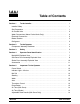
Table of Contents To the Installer . . . . . . . . . . . . . . . . . . . . . . . . . . . . . . . . . . . . . . . . . . . . 1 Installer Safety . . . . . . . . . . . . . . . . . . . . . . . . . . . . . . . . . . . . . . . . . . . . . . . . . . . . . . . . 1 Site Preparation . . . . . . . . . . . . . . . . . . . . . . . . . . . . . . . . . . . . . . . . . . . . . . . . . . . . . . . 1 Air Cooled Units . . . . . . . . . . . . . . . . . . . . . . . . . . . . . . . . . . . . . . . . . . . . . . . . . . . .
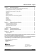
Table of Contents -- Page 2 Operating Procedures . . . . . . . . . . . . . . . . . . . . . . . . . . . . . . . . . . . . . 15 Prior To Set--Up For Units With A Syrup Rail (Optional Feature) . . . . . . . . . . . . . 15 Freezing Cylinder Assembly -- Soft Serve Side . . . . . . . . . . . . . . . . . . . . . . . . . . . . 15 Freezing Cylinder Assembly -- Shake Side . . . . . . . . . . . . . . . . . . . . . . . . . . . . . . . . 19 Sanitizing . . . . . . . . . . . . . . . . . . . . . . . . . . . . . . .
Section 1 To the Installer The following are general installation instructions. For complete installation details, please see the checkout card. This unit has many sharp edges that can cause severe injuries. Note: Only instructions originating from the factory or its authorized translation representative(s) are considered to be the original set of instructions. Installer Safety Site Preparation In all areas of the world, equipment should be installed in accordance with existing local codes.
Air Cooled Units Electrical Connections DO NOT obstruct air intake and discharge openings: In the United States, this equipment is intended to be installed in accordance with the National Electrical Code (NEC), ANSI/NFPA 70-1987. The purpose of the NEC code is the practical safeguarding of persons and property from hazards arising from the use of electricity. This code contains provisions considered necessary for safety.
Refrigerant S S S Stationary appliances which are not equipped with a power cord and a plug or another device to disconnect the appliance from the power source must have an all-pole disconnecting device with a contact gap of at least 3 mm installed in the external installation.
Section 2 To the Operator The freezer you have purchased has been carefully engineered and manufactured to give you dependable operation. The Taylor Model 632, when properly operated and cared for, will produce a consistent quality product. Like all mechanical products, this machine will require cleaning and maintenance. A minimum amount of care and attention is necessary if the operating procedures outlined in this manual are followed closely.
Section 3 Safety We, at Taylor Company, are concerned about the safety of the operator when he or she comes in contact with the freezer and its parts. Taylor has gone to extreme efforts to design and manufacture built--in safety features to protect both you and the service technician. As an example, warning labels have been attached to the freezer to further point out safety precautions to the operator. S DO NOT operate the freezer unless it is properly grounded.
This freezer must be placed on a level surface. Failure to comply may result in personal injury or equipment damage. DO NOT allow untrained personnel to operate this machine. S DO NOT operate the freezer unless all service panels and access doors are restrained with screws. S DO NOT remove any internal operating parts (examples: freezer door, beater, scraper blades, etc.) unless all control switches are in the OFF position.
Section 4 Operator Parts Identification Model 632 Exploded View 111101 Model 632 7 Operator Parts Identification
Model 632 Parts Identification List ITEM DESCRIPTION PART NO. ITEM DESCRIPTION PART NO. 1 COVER-HOPPER 053809 11 SCREW-1/4-20X3/8 RHM-SS 011694 2 TUBE-FEED-SHAKE-5/16 HOLE 028967-7 12 TUBE A.
Soft Serve Door Assembly Exploded View Item Description Part No. Item Description Part No. 1 Seal--Drive Shaft 032560 9b Screw--Adjustment 033662 2 Shaft--Beater 032564 9c O--Ring (Adjustment Screw) 015872 3 Beater A.--3.4 Qt. 1 Pin X31761 10 O--Ring 5/16 OD x .070 W 016272 4 O--Ring--3/8 OD x .070 W 016137 11 Pin A.--Pivot X22820 5 Blade--Scraper--Plastic 035174 12 Nut--Stud 021508 6 Bearing--Front 050216 13 Valve A.
Shake Door Assembly Exploded View Item Description Part No. Item Part No. 1 Seal--Drive Shaft 032560 Gasket--Door 016672 2 Shaft--Beater 032790 8 Door Assembly X30272--SER 3 Beater A.--7 Qt.--1 Pin X46233 9 Valve A.--Draw X13624--SP 4 Clip--Scraper Blade -- 8.
Accessories Item Description Part No. 1 Brush--Rear Bearing 013071 2 Brush--Double Ended 013072 3 Brush--Draw Valve 014753 4 Brush--Mix Hopper 023316 5 Lubricant--Taylor 4 oz. 047518 6 Pail--Mix 10 qt.
Section 5 Item Important: To the Operator Power Switch Description 1 Power Switch 2 Mix Low Indicator Light 3 Mix (Hopper Refrigeration) 4 Standby 5 Wash 6 Auto 7 Thermistor Control 8 Adjustable Draw Handle 9 Reset Button Important: To the Operator When placed in the ON position, the power switch allows SOFTECH control panel operation. Indicator Light -- Mix low Located on the front of the machine is a mix level indicating light.
Mix Ref Wash When the WASH key is pressed, the light comes on. This indicates beater motor operation. The STANDBY or AUTO modes must be cancelled first to activate the WASH mode. When the MIX REF key is pressed, the light comes on indicating the mix hopper refrigeration system is operating. MIX REF is controlled by the left side of the freezer as viewed from the operator end. The MIX REF function cannot be cancelled unless the AUTO or STANDBY modes are cancelled first.
Air Tube (Soft Serve) Air Tube (Shake) The air tube serves two purposes. One end of the tube has a hole and the other end does not. After priming the machine, install the air tube. Install the air tube in the position that will allow for the hole marked “1” to be in the down position. This is the AUTO position, and will allow mix and air to travel to the freezing cylinder while product is being dispensed. Figure 2 During long “No Sale” periods, reverse the position of the air tube.
Section 6 Operating Procedures Freezing Cylinder Assembly -- Soft Serve Side We begin our instructions at the point where we enter the store in the morning and find the parts disassembled and laid out to air dry from the previous night’s cleaning. These opening procedures will show you how to assemble these parts into the freezer, sanitize them, and prime the freezer with fresh mix in preparation to serve your first portion.
Insert the drive shaft into the freezing cylinder, hex end first, and into the rear shell bearing until the seal fits securely over the rear shell bearing. Engage the hex end firmly into the drive coupling. Be sure the drive shaft fits into the drive coupling without binding. Figure 6 Slide the beater the remainder of the way into the freezing cylinder and over the end of the drive shaft. The beater should fit snugly, but not so tightly that the beater cannot be turned slightly to engage the drive shaft.
Slide the two o--rings into the grooves on the prime plug. Apply an even coat of Taylor Lube to the o--rings and shaft. Step 5 Install the draw valve. Slide the two o--rings into the grooves on the draw valve, and lubricate. Figure 8 Figure 11 Insert the prime plug into the hole in the top of the freezer door, and push down. Lubricate the inside of the freezer door spout, top and bottom, and insert the draw valve from the bottom until the slot in the draw valve comes into view.
Slide the fork over the bar in the slot of the draw valve. Secure with pivot pin. Slide the small o--ring into the groove of the air orifice. Do not lubricate the o--ring. Figure 14 Note: These units feature adjustable draw handles to provide the best portion control. The draw handles can be adjusted for different flow rates. See page 14 for more information on adjusting these handles. Figure 17 Step 7 Snap the design cap over the end of the door spout.
Insert the drive shaft into the freezing cylinder, hex end first, and into the rear shell bearing until the seal fits securely over the rear shell bearing. Engage the hex end firmly into the drive coupling. Be sure the drive shaft fits into the drive coupling without binding. Freezing Cylinder Assembly -Shake Side Note: When lubricating parts, use an approved food grade lubricant (example: Taylor Lube). MAKE SURE CONTROL SWITCH IS IN THE “OFF” POSITION.
If blades are in good condition, install the scraper blade clips on the scraper blades. Place the rear scraper blade over the rear holding pin on the beater (knife edge to the outside). Holding the rear blade on the beater, slide the assembly into the freezing cylinder halfway, tail end first. Install the front scraper blade over the front holding pin. Slide the beater assembly completely into the freezing cylinder. Figure 24 Step 4 Install the freezer door.
Sanitizing Rotate the draw valve bracket to the left and center it into position by raising the draw arm and placing it into the slotted groove of the draw valve bracket. Step 1 Prepare a pail of approved 100 PPM sanitizing solution (examples: 2--1/2 gal. [9.5 liters] of Kay--5R or 2 gal. [7.6 liters] of Stera--SheenR). USE WARM WATER AND FOLLOW THE MANUFACTURER’S SPECIFICATIONS. Note: The draw valve bracket must be positioned with the notch to the left.
Step 7 When a steady stream of sanitizing solution is flowing from the prime plug opening in the bottom of the freezer door, open the draw handle. Draw off all the sanitizing solution. Step 4 Place the power switch in the ON position. Figure 31 Step 5 Press the WASH key. This will cause the sanitizing solution in the freezing cylinder to agitate. Allow it to agitate for five minutes.
Priming Step 1 With a pail beneath the door spout, open the draw handle. Be sure the prime plug is still in the UP position (soft serve side only). Pour two gallons (7.6 liters) of fresh mix into the mix hopper and allow it to flow into the freezing cylinder. This will force out any remaining sanitizing solution. When full strength mix is flowing from the door spout, close the draw handle. Note: Use only fresh mix when priming the freezing cylinder. Figure 38 Step 5 Press the AUTO key.
Closing Procedure Rinsing Step 1 Pour two gallons (7.6 liters) of cool clean water into the mix hopper. With the brushes provided, scrub the mix hopper, mix inlet hole and mix level sensing probe. To disassemble your unit, the following items will be needed: S S S S S Two cleaning pails Sanitized stainless steel rerun can with lid Step 2 With a pail beneath the door spout, (raise the prime plug -- soft serve only) and press the WASH key.
Note: To remove o--rings, use a single service towel to grasp the o--ring. Apply pressure in an upward direction until the o--ring pops out of its groove. With the other hand, push the top of the o--ring forward and it will roll out of the groove and can be easily removed. If there is more than one o--ring to be removed, always remove the rear o--ring first. This will allow the o--ring to slide over the forward rings without falling into the open grooves.
Section 7 Important: Operator Checklist During Cleaning and Sanitizing prime the machine with rerun. When using rerun, skim off the foam and discard. Mix the rerun with fresh mix in a ratio of 50/50 during the days operation. ALWAYS FOLLOW LOCAL HEALTH CODES. j 6. On a designated day of the week, run the mix as low as feasible and discard it after closing. This will break the rerun cycle and reduce the possibility of high bacteria and coliform counts.
Winter Storage CAUTION: Always disconnect electrical power prior to cleaning the condenser. Failure to follow this instruction may result in electrocution. If the place of business is to be closed during the winter months, it is important to protect the freezer by following certain precautions, particularly if the building is subject to freezing conditions. j 7. If your machine is equipped with an auxiliary refrigeration system, check the auxiliary condenser for accumulation of dirt and lint.
Section 8 PROBLEM 1. 2. 3. No product is being dispensed with draw valve open and the machine in the AUTO mode. The product is too stiff. The product is too soft. Troubleshooting Guide PROBABLE CAUSE REMEDY PAGE REF. a. Freeze--up in mix inlet hole. a. Call service technician to adjust the mix hopper temperature. ------ b. Beater motor out on reset. b. Reset the freezer. c. The beater is rotating counterclockwise from the operator end. c.
PROBLEM 6. 7. 8. 9. The drive shaft is stuck in the drive coupling. The freezing cylinder walls are scored. Excessive mix leakage into the rear drip pan. Excessive mix leakage from door spout. 10. No freezer operation after pressing the AUTO key. 11. Product is not feeding into the freezing cylinder. Model 632 PROBABLE CAUSE REMEDY PAGE REF. a. Rounded corners of drive shaft, coupling, or both. a. Call service technician to correct cause, and to replace the necessary components.
Section 9 Parts Replacement Schedule PART DESCRIPTION EVERY 3 MONTHS EVERY 6 MONTHS ANNUALLY White Bristle Brush, 3” x 7” Inspect & Replace if Necessary Minimum White Bristle Brush, 1” x 2” Inspect & Replace if Necessary Minimum Black Bristle Brush, 1” x 2” Inspect & Replace if Necessary Minimum Double--Ended Brush Inspect & Replace if Necessary Minimum Drive Shaft Seal X *Scraper Blade (Soft Serve) X Freezer Door Gasket X Front Bearing X Draw Valve O--Ring X Pivot Pin O--Ring X
Model 632 ADAPTOR A.-CASTER BEARING-FRONT BEARING-FRONT BEARING-REAR SHELL *NICK.PLATE +GUIDE-DRIP SEAL +NUT-BRASS BEARING +WASHER-BEARING LOCK BEATER A.-3.4QT-HELICORE +BLADE-SCRAPER-PLASTIC 17L BEATER A.-7QT-1 PIN-SUPPORT +BLADE-SCRAPER-PLASTIC 9-13/16L +CLIP-SCRAPER BLADE*8.75 INCH* BELT-AX39 BELT-AX41 BLOCK-TERMINAL 2P-L1,L2 BLOCK-TERMINAL 3P-L1,L2 BLOWER A. BOOT-CAPACITOR INSULATING CAPACITOR-RUN 7.5UF/370V MOTOR-FAN 208-230V 50/60 HZ BOARD-LOGIC-GEN 2.
+ Available Separately Parts List 32 Model 632 COMPRESSOR M63B203BBCB-BRISTOL +CAPACITOR-RUN 40MF/440V +CAPACITOR-START 145-175UF/250V +RELAY-START-COMPRESSOR COMPRESSOR L64A113BBCA-BRISTOL +CAPACITOR-RUN 25UF/440V +CAPACITOR-START 189-227UF/330V +RELAY-START-COMPRESSOR COMPRESSOR M63B203DBDB COMPRESSOR L63A113DBLA COMPRESSOR TL3G-R134A - DANFOSS +CAPACITOR-START 60UF-220/275V +COVER-TERMINAL-COMPRESSOR +KIT-MOUNTING-COMPRESSOR +RELAY-START-COMPRESSOR-TL3G COMPRESSOR-CS18K6E - COPELAND +CAPACITOR-RUN 35
+ Available Separately Model 632 33 Parts List CONDENSER-AC-7X6X1.25-2 ROW COUPLING-DRIVE 1/2 SQ. X 1-7/8 COUPLING-DRIVE 3/4 HEX X 1-7/8 COVER-HOPPER *GRAY* DECAL-CLEAN INST.-HOPPER DECAL-DEC-TWIN-SS DECAL-POWER SWITCH DECAL-TROUBLESHOOTING DEFLECTOR-BLOWER EXHAUST DIAGRAM-WIRING *632*HP62* DIAGRAM-WIRING *632*HP62* DOOR A.-1 SPOUT-7 QT +DECAL-LIFT PLATE FRONT +VALVE A.-DRAW +O-RING-1-1/16 OD X.139W DOOR A.-1 SPOUT *VALOX* +BEARING-FRONT +GASKET-DOOR HT 4"-DOUBLE +HANDLE A.-DRAW-ADJ. +O-RING-1/4 OD X .
+ Available Separately Parts List 34 Model 632 GUIDE A.-DRIP PAN *632* HOOD *632* KIT A.-COMPRESSOR-DANFOSS +DRYER-CAP. TUBE .026ID X 13FT KIT A.-MOTOR-FAN KIT A.-TUNE UP*440-441-444* BEARING-FRONT GASKET-DOOR 5.177ID X 5.938OD O-RING-.643 OD X .077W O-RING-1-1/16 OD X.139W O-RING-5/16 OD X .070W SEAL-DRIVE SHAFT TOOL- 0-RING REMOVAL KIT A.-TUNE UP-1 SPOUT-NON HT BEARING-FRONT CAP-DESIGN-1.010"ID-6 POINT GASKET-DOOR HT 4"-DOUBLE O-RING-.643 OD X .077W O-RING-3/8 OD X .070W O-RING-5/16 OD X .
+ Available Separately Model 632 35 Parts List 047518 030049-M 013102-27 021522-27 013102-33 021522-33 053481-27 062253-27 021508 022465-100 016137 013163 027503 X49546 067577 067578 X44853 X44855 053782 017563 024439 028932 028933 032961 036642 027422 X30922 X31602 X50717 016403 039695 007471 NUT-STUD *GENERAL USAGE* ORIFICE +O-RING-3/8 OD X .070W PAIL-MIX 10 QT. PAN-DRIP 11-5/8 LONG PANEL A.-FRONT*632*HP62 PANEL-SIDE *632* RIGHT PANEL-SIDE *632* LEFT PANEL A.-SIDE *342*770C*LWR*L PANEL A.
+ Available Separately Parts List 36 Model 632 051013 X33321 066795-33 032607-27 041082 032564 032560 032790 032560 X67587-SP 022822 X49788 022822 X49785 022822 037041 066794-27J 066794-27K 066794-33H 066794-33J X33329-SER X33332 X33330 024908 038623 027219 023487 028889 X49552-SER X51677 STARTER-1 PHASE 6.3 TO 10 AMP STARTER-3 PHASE 2.5 TO 4 AMP STARTER-3 PHASE 4 TO 6.5 AMP SWITCH A.-DRAW *632*MIX CAB ARM A.-DRAW VALVE *755 MC* BRACKET A.
+ Available Separately Model 632 37 Parts List ACCUMULATOR-COPPER 2"DIA 10" BLOWER-100 CFM CLAMP-HOSE 3/4 ID CONST TENSN CONDENSER-WC-COAX GUARD-BLOWER HOSE-RUBBER 1/2 ID X 7/8 OD OUTLET A.-TEE PANEL-REAR PIPE TEE 3/8-WATER VALVESHIELD-SPLASH-WIRE 21-11/16 WATER COOLED BRACKET A.-SWITCH BRACKET A.-SWITCH E-RING EXTERNAL 1/2 SCREW-4-40 X 5/8 RHM-ZP STEEL SPRING-RETURN L.
+ Available Separately Parts List 38 Model 632 023874 039423 024156 039421 039424 048259-33 062274-33 062274-40 029439 033044-1 062366 048259-40 023739 031790 038146 062274-58 048259-58 049443-35 049443-40 049443-58 013102-35 021522-35 013102-34 BLOCK-TERMINAL 3P L1,L2,L BLOCK-TERMINAL 7P GREEN BLOCK-TERMINAL 2P L1,N BLOCK-TERMINAL 4P L1,L2,L3,N COMPRESSOR L63A113DBLA COMPRESSOR M63B203DBDB COMPRESSOR M63B203BBKB SHAKE +CAPACITOR-RUN 35UF/370V +CAPACITOR-START 189-227UF/33 +RELAY-START-COMPRESSOR COMP
+ Available Separately Model 632 39 Parts List 066795-33 RELAY-3 POLE-20A-208/240 046170 037041 066794-33H 066794-33J 066794-27J 066794-27K 046171 014533 016055 007538 PULLEY-AK34-5/8 PULLEY-AW62-5/8 SHIELD-SPLASH-WIRE 21-11/16 SHIELD-SPLASH STARTER-3 PHASE 2.5 TO 4 STARTER-3 PHASE 4 TO 6.5 AMP STARTER-1 PHASE 4 TO 6.5 AMP STARTER-1 PHASE 6.
+ Available Separately Parts List 40 Model 632 COVER-LIFT OFF W/PLAIN KNOB FAUCET-CENTRAL 4 IN. CENT +PLATE-FAUCET HOOD *632* W/FAUCET HOLES JAR-3 QT. PLAS. KIT A.-TUNE UP BEARING-FRONT BEARING-FRONT CAP-DESIGN-1.010"ID-6 POINT GASKET-DOOR 5.177ID X 5.938O GASKET-DOOR HT 4"-DOUBLE GASKET-DOOR-4" SHELL O-RING-.643 OD X .077W O-RING-1-1/16 OD X.139W O-RING-3/8 OD X .070W O-RING-5/16 OD X .070W O-RING-7/8 OD X .103W SEAL-DRIVE SHAFT TOOL- 0-RING REMOVAL LADLE-1 OZ. PAN A.-DRIP-EXP.VLV PANEL A.
+ Available Separately Model 632 41 Parts List FILTER-CORCOM 2VR1 HOOK-UPPER SPINNER MOTOR-SPINNER MODEL 22-230 PLATE A.-SWITCH *SPINNER A.* PLATE-REAR UPPER SCREW-SPINNER DISC SCREW-FLUTED SPINNER DISC SHIM-SWITCH STUD-1/4-20 X 2 1/4 STL.ZP SWITCH-SNAP-SPDT-20A/125-250 TUBE-VINYL 1/4ID X 1/16WALL DESCRIPTION 032567 011173 020101-27 X34363 013835 013660 051431 035515 020102 013192 020941-48 PART NUMBER 1 1 1 1 1 1 1 1 1 1 2 QTY. 103 103 103 103 103 103 103 103 103 103 000 WARR.
Model 632 049443-27 2/12
Model 632 049443-33 2/12
Model 632 049443-35 2/12
Model 632 049443-40 2/12
Model 632 049443-58 2/12