P2 LEVEL PILOT ADMINISTRATOR’S MANUAL
IMPORTANT SAFETY INSTRUCTIONS The lightning flash with an arrowhead symbol within an equilateral triangle, is intended to alert the user to the presence of uninsulated "dangerous voltage" within the product's enclosure that may be of sufficient magnitude to constitute a risk of electric shock to persons.
IMPORTANT SAFETY INSTRUCTIONS EMC / EMI. This equipment has been tested and found to comply with the limits for a Class B Digital device, pursuant to part 15 of the FCC rules. These limits are designed to provide reasonable protection against harmful interference in residential installations. This equipment generates, uses and can radiate radio frequency energy and, if not installed and used in accordance with the instructions, may cause harmful interference to radio communications.
TABLE OF CONTENTS INTRODUCTION ALGORITHM Important Safety Instructions & Certificate of conformity . . . . . . . . . .a-b Table of Contents . . . . . . . . . . . . . . . .3 Introduction . . . . . . . . . . . . . . . . . . . . .4 Quick Start . . . . . . . . . . . . . . . . . . . . .5 Front Panel Overview . . . . . . . . . . . . .6 Rear Panel Overview . . . . . . . . . . . . .8 Signal Flow Diagram . . . . . . . . . . . . . .9 Typical P2 Setups . . . . . . . . . . . . . . .
INTRODUCTION Welcome The P2 is a “set and forget” Loudness pilot and Limiter for Post production and Broadcast. It is designed especially for fixed installations where a consistent loudness and spectral balance is required but excels also in peak limiting functions. Factory loaded with a broad selection of World Standard Presets the P2 can be used right out of the box.
QUICK START Daily User Requirements The P2 is correctly connected and loaded with relevant Front Presets by the Administrator and powered on. Lock The Administrator can decide to activate different levels of Lock functions. These may include lock of front panel key operation and/or lock of the Wizard and Bypass functions.
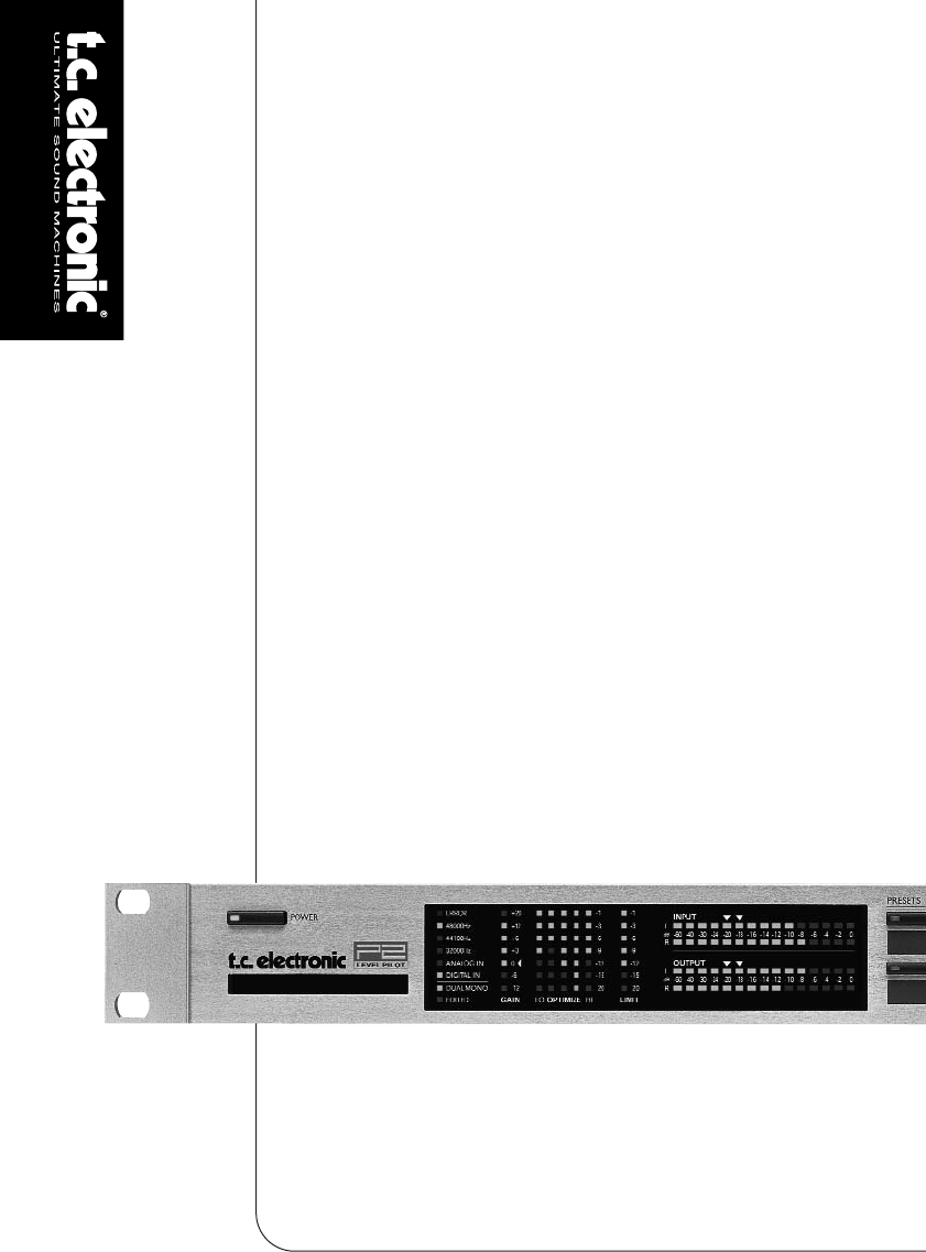
FRONT PANEL OVERVIEW POWER On/Off Switches power On/Off. To completely disconnect from mains the Rear panel POWER switch must be used. PCMCIA slot For software updates and preset backups. ERROR LED Indicates various error states. 48/44.1/32 kHz LEDs Indicates current Sample Rate. ANALOG IN/DIGITAL IN Indicates currently selected Input type. DUAL MONO LED Indicates that the P2 is operating in Dual mono mode. EDITED LED Indicates that the currently recalled preset has been edited but not stored.
FRONT PANEL OVERVIEW PRESET keys 1-8 Presets can be recalled from these keys. Press preset keys 1-8 to instantly recall Front presets. This type of presets include settings of all gain and processing parameters. Keys can be locked by the Administrator. Below each key you can write preset names. Use the supplied lithographic crayon or similar.
REAR PANEL Power Input 100 - 240V Power Switch Balanced Analog Inputs XLR Balanced Analog Outputs XLR AES/EBU Input/ Output S/PDIF Input/ Output RS 232 9 pin Sub D GPI IN RS232 : For connecting to a PC. Use a standard 9 pin Sub D cable. (Supplied) GPI In BNC : Use standard stereo 1/4” jack. (not supplied) : Use standard shielded 75 Ohm Coax cable with BNC connectors.
SIGNAL FLOW 9
TYPICAL SETUPS Connecting and Setting up the P2 In use - no TC Icon Editor/PC connection necessary. • Connect your audio source material to P2 Inputs. Options are balanced Analog, digital AES or S/PDIF. • Connect Outputs to relevant media. • Select preset via the eight front panel PRESET keys. Note that; Input type, Sync settings, and Sample Rate Conversion settings are set on preset level via the TC Icon PC Editor on the Engine I/O page.
BASICS - FRONT PANEL Two levels of P2 operation First of all the “every-day-use” where the less experienced user basically selects predefined presets and occasionally the Wizard that intelligently analyze program material and suggests compression settings for that particular material. Secondly the “Administrators level” accessed only via the TC Icon Software Editor on PC. This is where Presets, I/O, Wizard, Lock and System settings are setup.
FRONT PANEL OPERATION Lock Recall: No presets can be recalled via the eight front panels preset keys and the Wizard function is also disabled. Lock Panel: The entire front panel, recall functions, Bypass and Card dump functionality is disabled. Bypass The function of the front panel BYPASS key is set via the System Front page on the TC ICON editor. Four Bypass modes are available: • Normal: No delay in bypass. Dither active. • Relay: Bit transparent digital plus analog Bypass relay.
INSTALLATION - OF THE TC ICON SOFTWARE EDITOR Requirements for running the TC Icon Software Editor • A Pentium PC, or compatible, with any of the following operating systems: Windows 95, Windows 98, Windows NT, Windows 2000, Windows ME or Windows XP. The CD-ROM The CD delivered with the TC Icon Software Editor contains: • A folder called: TC Icon Software Editor update version. Use this if the MS Installer* is already on your computer.
THE TC ICON EDITOR Introduction The TC Icon Software Editor is a generic Editor that currently controls the following products by TC Electronic: System 6000, DB-8 and P2. In this section only subjects relevant for usage with the P2 will be discussed. Another active application may conflict with the selected COM Port. If this is the case you should close that application or connect the P2 to another COM port. Also see Trouble-shoot section in this manual • Then go to the TC Icon Setup/Devices page.
THE TC ICON EDITOR Basic Operation The Icon Link key in the upper left corner allows you to navigate between two main pages/modes. Fig 1 - Setup/Select page Library pages handle operations such as preset Recall/Store and Delete. System pages handle overall Clock Settings, I/O settings and network settings. Engine pages is where you control all algorithm specific processing parameters. Renaming presets All user presets can easily be renamed.
PRESET STRUCTURE - RECALL/STORE/DELETE Library Pages Engine Presets These are the pages from where all preset handling is controlled when using the TC Icon Editor. Engine presets holds all parameters and settings from the Engine page. To recall a preset: • Simply select the desired preset by clicking on the preset name in the list. • Then press the RECALL button Preset List Recall button User presets The User banks U1 to U8 can hold up to 8 presets each.
BASICS - PRESET HANDLING To delete a preset • Select the Delete page by pressing the DELETE side tab. • Select the preset you wish to delete. Press DELETE. When Presets are Stored or Deleted, parameters from the In/Out page and Engine Layers are always affected. System parameters on the other hand are unaffected by any other commands than a specific System Store or System Delete. Bank Handling Via the Library-Bank page it is possible to: • Backup and retrieve the System User bank.
CLONING P2’S Cloning P2’s Creating the Clone Card To easily clone multiple P2’s a PCMCIA card is used. • Load appropriate presets into Front Panel Bank of the P2 you wish to clone. • Insert a 512kb or 1Mb PCMCIA card in the Card slot on the P2 front panel. • Go to the System Card page. • Decide whether you wish to exclude System Preset 1 that holds overall Clock settings, Analog Trim levels, Dither, Status Bit settings and settings for GPI. To exclude System Preset activate the “Exclude System Preset” key.
SYSTEM - I/O PAGE Digital Output Dither Range: 8, 12, 14, 16, 18, 20, 22, 24, off P2 processes internally at 48 bit resolution. Dither must be set to match downstream devices. Status Bits Select whether the P2 should send out AES/EBU or S/PDIF status bit information. GPI Via an external Fader or alternating (latching) switch various functions can be controlled. Parameters on the System page can be stored and recalled via System presets and are unaffected by normal Recall operations.
SYSTEM - I/O PAGE bet ee 8 p esets RL1 off on tip RL1 ring nc preset 1 preset 2 GPI Input RL3 Select 1 of 2 R3, 47k sleeve RL2 R2, 22k RL2 off off on on RL2 R2, 22k RL1 off on off on preset 1 preset 2 preset 3 preset 4 RL3 off off off off on on on on RL2 off off on on off off on on tip RL1 R1, 12k RL1 off on off on off on off on nc ring preset 1 preset 2 preset 3 preset 4 preset 5 preset 6 preset 7 preset 8 GPI Input Select 1 of 8 sleeve tip RL1 nc R1, 12k GPI Input ring Select 1 of 4
SYSTEM - FRONT PAGE If GPI Preset mode is selected and no connections are made to the GPI Input the P2 will always recall preset 1 at power up. Front Panel Configuration On this page various preferences for the Front panel controls are set. Delay Frame compensation Delay. Actual Delay time can be tapped using a connected momentary switch. Calibrate Wizard Mode Use this function to calibrate P2 to a connected GPI controller. E.g. TC Master Fader (not supplied).
SYSTEM - NET PAGE & ICON VIEWS Disable: No lock function is active. Lock Wizard: Wizard function is disabled and cannot be activated via the front panel WIZARD key. Lock Recall: No presets can be recalled via the eight front panels preset keys but the Wizard function is enabled. Lock Panel: The entire front panel, recall functions, Bypass and Card dump functionality is disabled. Lock Activation The two Lock activation modes defines how the Lock function can be activated/deactivated from the front panel.
I/O PAGE Fader at right side No faders Input & Clock Input Select Range: Analog, Digital Select appropriate Input type. Digital Input Select Range: AES/EBU, S/PDIF Select type of digital Input format. Clock Select Range: Internal 44.1, Internal 48k, Word Clock, Ext DI Select to which clock the P2 should sync. Digital SRC Range: On/Off Sets whether the P2 should perform Sample Rate conversion on the incoming clock or not. Color Page Select a color scheme to your liking or make your own.
MAIN PAGE In Gain Range: 0dB to Off Separate level controls for Left and Right Input (A and B). Phase Inv Range: Normal/Inverted Press to phase invert channels A, B or both. Delay Range: 0-1000ms Delay alignment of the Input channels. Depending on selected Configuration type, either one common Delay setting or individual delay settings are available. Delay Unit Range: ms, 24fps, 25fps, 30fps With this parameter it is possible to select which unit the Delay parameter should be shown in.
MAIN PAGE Configuration Processing Overview 5-BAND Analog DELAY FILTERS AGC Hi Band EQ LIMIT Hi Mid In Out In Out In Out In Out Mid In Lo Mid Digital Ana Digi Lo Band Limit: Link/Unlink Delay: Link/Unlink 5-BAND Analog DELAY FILTERS AGC Hi Band EQ LIMIT Hi Mid In Out In Out In Out In Out Mid Lo Mid Digital 24 Bit 48 Bit Lo Band In Ana Digi 24 Bit Configuration Reference Level Reference Level defines the standard operating level, and scales the Threshold and Target
MAIN PAGE LOUDNESS PAGE Processing Modes - Stereo. In this mode the Loudness, EQ and Multiband sections operate in tandem: Whatever gain change is applied to one channel, is applied to the other. Also, many parameters have mutual left and right controls. - Dual Mono. In this mode the Loudness, EQ and Multiband sections treat the two Input signals completely independently. - Stereo Wide.
LOUDNESS PAGE Average Rate (Avg Rate) Time constants in the Loudness Control are changed dynamically with the Input signal based on computations by multi-level detectors. When the Output level is close to the Target Level, gain changes are relatively slow. The Average Rate offsets all time constants to be faster or slower. Values below 1dB/Sec produces a gain change gating effect when the Output level is already in the target zone, while values above 4dB/Sec will add density to sound.
EQ PAGE EQ Page Introduction This digital EQ features a three-band parametric EQ with high- and low-pass filters switchable between Notch, Parametric, Shelving and Cut filters. The needle sharp notch filter has a range down to 0.01 octave and the shelving filters has a variable slope, ranging from gentle 3 dB/oct over 6 and 9 to 12dB/oct. Cut filters are switchable between 12dB/oct maximum flat amplitude (Butterworth) or flat group delay (Bessel) types.
EQ PAGE Shelving Filter Cut Filter - Butterworth type Notch Filter - Narrow Type Freq Press Freq and use Faders 1 to 3 to adjust frequence for each of the three bands. Range - Lo band Range - Mid band Range - Hi band : 20Hz to 20kHz : 20Hz to 20kHz : 20Hz to 40kHz Gain Press Gain and use Faders 1 - 3 to adjust gain for each of the three EQ bands.
EQ PAGE Type Press TYPE and use Faders 1-3 to set BW value for each of the three EQ bands. Range for the Notch filter: Lo BW : 0.02oct to 1oct Mid BW : 0.02oct to 1oct Hi BW : 0.02oct to 1oct Range for the Parametric filter: Lo BW : 0.1oct to 4oct Mid BW : 0.1oct to 4oct Hi BW : 0.1oct to 4oct Range for the Shelve filter: Lo BW : 3dB/oct to 12dB/oct Hi BW : 3dB/oct to 12dB/oct Range for the Cut filter: Lo BW : Bessel or Butterworth Hi BW : Bessel or Butterworth Bandwidth/Q - Key-Values: BW Q 0.5 2.87 0.7 2.
5-BAND PAGE DXP Mode - introduction The 5-band section is either in normal compression mode, or DXP mode. Instead of attenuating signals above a certain threshold, DXP mode (Detail Expansion) lifts up signals below the Threshold; thereby bringing out details rather than squashing the loud parts. DXP mode therefore is capable of adding intelligibility and air to speech, lifting harmonics, or emphasizing ambience without increasing overall peak level.
5-BAND PAGE LIMITER Try setting the Steer and/or Threshold parameters differently in the bands to hear the effect. High Steer values add more detail gain than low values, but remember that Threshold has to be negative to add detail gain at all. DXP Threshold relates to the Reference Level set on the Main page. To disable DXP detail gain at very low levels, use the Defeat Threshold and Defeat Ratio controls.
LIMITER APPENDIX peaks from reaching the Output, and timeconstants adapt to the Input signal. Reset menu & software load Fader A & Fader B Parameter range: Off to 0dB Fader function on the Output. When Dual Mono configuration is selected, individual Output faders are available. To enter the following functions hold WIZARD key while powering up the unit. Once entered this menu navigation is as follows: • Press PRESET keys 4 and 8 to scroll in menu.
APPENDIX TROUBLESHOOTING Loading Preset Banks Port Conflict The P2 is loaded with the 8 presets from the Default F1 bank (see page 37). These are the presets accessible from the Front Panel . However, it is possible to load other banks into the front panel. To do this: Another active application may conflict with the serial ports you have selected on the: Setup - Devices - Ports page. If this is the case the following screen will appear. • Press and hold LOCK when powering up. All key LEDs will flash.
APPENDIX - TECHNICAL SPECIFICATIONS Digital Inputs and Outputs Connectors: Formats: Output Dither: Word Clock Input: Sample Rates: Processing Delay: Additional Delay: Frequency Response DIO: XLR (AES/EBU), RCA Phono (S/PDIF) AES/EBU (24 bit), S/PDIF (24 bit), EIAJ CP-340, IEC 958 HPF TPDF dither 8-22 bit BNC, 75 ohm, 0.6 to 10 Vpp 32 kHz, 44.1 kHz, 48 kHz 0.5 ms @ 48 kHz 0-1000 ms at all sample rates DC to 23.9 kHz ± 0.
SELF TEST Available from Software 1.20 and up. Accessing Self test • Press and hold the “BYPASS” key, while powering up to access the self test. • Press PRESET 8 to increase test number. • Press PRESET 4 to decrease test number. • Press LOCK to enter a test and acknowledge OK result. • Press BYPASS to acknowledge bad result. • The test number is shown in the OPTIMIZE display. The self tests are described below. Test 0 - LED test Turns all LEDs on.
PRESET LIST - SW 1.50 Screen Notes Input Max Scale Design Notes Analog Input Limiter. US Std. SMPTE RP155 Digital Input Limiter. US Std. SMPTE RP155 Analog Input Limit. EU Std. EBU R68 Digital Input Limit. EU Std. EBU R68 Analog Dual Input. US Std. SMPTE RP155 Digital Dual Input. US Std. SMPTE RP155 Analog Input Wide Range ALC. EBU R89 Digital Input Wide Range ALC. EBU R89 Ana -6 +24 Digi -6 +24 Ana -9 +18 Digi -9 +18 Ana -6 +24 SMPTE RP155 (adj. 1.10) SMPTE RP155 (adj. 1.
PRESET LIST - SW 1.50 No Name F4 Reserved 1 2 3 4 5 6 7 8 Reserved Reserved Reserved Reserved Reserved Reserved Reserved Reserved F5 Live Mix 1 Mix Pilot 2 News 3 Gameshow 4 Live Sports 5 6 7 Reserved Reserved OptiLink, Dual Screen Notes Input General purpose Mix Assistant. Digital In News Mix Assistant. Digital In, Dual Mono Gameshow Mix Assistant. Digital In Live sports Mix Assistant.
PRESET LIST - SW 1.50 No Name F7 Reserved 1 2 3 4 5 6 7 8 Reserved Reserved Reserved Reserved Reserved Reserved Reserved Reserved F8 Live Mix 1 STL Relax 2 STL Energy 3 STL Sky 4 STL Autobahn 5 STL Signature 6 7 8 Reserved Reserved Reserved Screen Notes Input Max Scale Radio STL Optimize. Shape: Flat Radio STL Optimize. Shape: Loudness Radio STL Optimize. Shape: Crisp Radio STL Optimize. Shape: Core Radio STL Optimize.