USER’S MANUAL Finalizer PLUS/96K STUDIO MASTERING PROCESSOR
TABLE OF CONTENTS INTRODUCTION Table of contents . . . . . . . . . . . . . . . . . . 3 Welcome . . . . . . . . . . . . . . . . . . . . . . . . 5 Front Panel . . . . . . . . . . . . . . . . . . . . . . 6 Rear Panel . . . . . . . . . . . . . . . . . . . . . . 8 Signal flow diagram . . . . . . . . . . . . . . . . 9 Finalizer setup . . . . . . . . . . . . . . . . . . . 10 BASIC OPERATION Recall . . . . . . . . . . . . . . . . . . . . . . . . . 12 Store . . . . . . . . . . . . . . . . . . . . . . . . . .
WELCOME Congratulations on the purchase of your new Finalizer PLUS/96. We hope that you will have as much pleasure using it, as we had making it. The Finalizer PLUS/96 is the result of an intense research process combined with the experience and unique creativity of TCs Research and Development group. The Finalizer PLUS/96 gives you all the tools you need to put the finishing touch on your mix.
FRONT PANEL SOFTCLIP LED Indicates when the Soft Clipper is active Output PPM High resolution meters POWER SOFTCLIP OVERLOAD 48000Hz 44100Hz OUTPUT L dB -60 -48 -44 -40 -36 -32 -30 -28 -26 -24 -22 -20 -18 -16 -14 -12 -10 -8 -6 -5 -4 -3 -2 -1 -0.5 0 R 32000Hz EXP MIDI IN Normalizer LIM POWER & MEMORY CARD Electronic power switch »Easy touch« Turn on the machine with a single light touch. To turn off the machine you must press and hold down the POWER key approx.
ADJUST wheel Sets parameter values and preset numbers. PROGRAM FUNCTIONS SOFTCLIP OUTPUT L dB -60 -48 -44 -40 -36 -32 -30 -28 -26 -24 -22 -20 -18 -16 -14 -12 -10 -8 -6 -5 -4 -3 -2 -1 -0.
REAR PANEL Main Power Power Input Switch Balanced XLR Inputs Balanced XLR Outputs Serial no. Wordclock Sync Input Digital In/Out AES/EBU S/PDIF, ADAT Tos-link MIDI In, Thru, Out Pedal/ Fader Input The Sync In This word clock Input gives you the following functions: - External reference for A/D or D/A - External reference for Sample Rate Conversion - External reference for Digital Inputs The Input impedance is 75 ohm.
SIGNAL FLOW Notes regarding the signal flow: Since the Finalizer is using 24 A/D-D/A converters, Dithering is available on Digital Outputs only.
FINALIZER SETUP Finalizer Setup The Finalizer is carefully designed to optimize the overall level and enhance the energy and clarity in your mix. The use of the three band Compressor, Limiter and Expander makes the dynamics section of the Finalizer very flexible, while maintaining the fidelity of the original material. The dynamics section, in a combination with a Normalizer and a five band Equalizer, gives you a very powerful tool, to finish the last details of your mix.
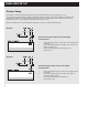
FINALIZER SETUP Example 3 Mastering from DAT to DAT 1. 2. Example 4 Connect the Digital Output of DAT #1 to the Digital Input of the Finalizer. Connect the Digital Output of the Finalizer to the Digital Input of DAT #2. Using the Finalizer with ADAT and BRC 1. 2. 3. Connect the Finalizers optical out to the ADATs optical in. Connect the ADATs optical out to the Finalizers optical in. Enter the In section of the Finalizer (Main page) and set the "Clock" to "ADAT".
RECALL ROM bank RAM bank Select which blocks to load from new preset. Preset name Preset number Short info about the preset Recalling a preset Press the RECALL key in the Program section and scroll through the presets using the ADJUST wheel. Press OK to recall when you find the desired preset. You are able to search for another preset before recalling it. This is called previewing. Until you press OK you are previewing.
STORE Storing a User preset and handling preset names Storing a preset with the same name: - Press the STORE key - Select a location for your new preset using the ADJUST wheel (You can store your preset in the RAM bank only, and the Finalizer therefore automatically selects this bank) - Press OK and the preset is stored with the same name at the selected location Storing a preset with a new name: - Move the cursor, using the MENU keys, to select the name line - Type the new preset name.
MAIN PAGE Input INPUT I1 I2 Insert In page no 1 Sample Rate Conversion on/off NORMALIZER Input type select Clock select EXPANDER Mode selector Digital Output formats Select the In section on the Main page using the BLOCK keys. The global level controls should be set to optimize the performance of the 24 bit A/D converter in the Finalizer. The In block is divided into two pages accessible by using the MENU keys.
MAIN PAGE Input Sample Rate Conversion may be applied to the AES/EBU, S/PDIF or Tos-link Input. The Input Sample rate is asynchronous, with the Output of the Sample Rate Converter locked to the system Clock source. Internal references at 44.1and 48 or an external Word Clock signal may be used to drive the Sample Rate Converter. Sample Rate LEDs When a Digital Input is used, and the signal is recognized, one of the three yellow Rate LEDs light up.
MAIN PAGE Input Finalizer & ADAT When using the Finalizer in a setup with ADATs there are a couple of recommendations to keep in mind. There are two different situations: An ADAT setup with BRC (Big Remote Control), and an ADAT setup without BRC. If the BRC is not connected, the ADAT should be slaved to incoming Finalizer Clock. Use the following: 1. Connect the Finalizers optical out to the ADAT optical in. 2. Select "Digital in" on the ADAT. The ADAT will now use the Finalizer clock.
This page is intentionally blank 17
MAIN PAGE Inserts INPUT I1 I2 NORMALIZER DIGITAL RADIANCE GENERATOR Insert type selector Select between: - None - Digital Radiance - Stereo Adjust - Dyn EQ - Parametric EQ - External Insert - MS Encoding/Decoding - Spectral Stereo Image (Finalizer 96 only) STEREO ADJUST EXPANDER COMPRESSOR LIMITER OUTPUT Insert selected Shows the performance of the Digital Radiance Generator This parameter determines the drive of the Digital Radiance Generator Move cursor up to increase the stereo width Move cur
MAIN PAGE Inserts Inserts Dynamic Equalizer Select Insert 1 or 2 using the BLOCK keys The Finalizer has various Insert possibilities. Choose between: None, DRG (Digital Radiance Generator), Stereo Adjust, Dynamic EQ, Parametric EQ, Ext Insert or MS Encoding/ Decoding or Spectral Stereo Image (only available in Finalizer 96). The Dynamic Equalizer is somewhat like an extended De-esser with more parameters and enlarged frequency range, enabling better control.
MAIN PAGE Inserts INPUT I1 I2 NORMALIZER Black box indicates selected block Level bar Frequency EXPANDER LIMITER OUTPUT Selected band Gain Bandwidth/Slope EQ Insert Type External Insert Basic operation Press the PARAMETER keys to select frequency/gain/ bandwidth/slope. Turn ADJUST wheel to change values. Press BAND keys to jump between the five bands. EQ Ranges Type Low Shelve Bell-shaped filter 1 Bell-shaped filter 2 Bell-shaped filter 3 High Shelve Frequency 19.95Hz to 5.01kHz 19.
MAIN PAGE Inserts INPUT I1 I2 NORMALIZER EXPANDER COMPRESSOR LIMITER OUTPUT Balance adjust MS Encoding/Decoding MS miking technique or Mid/Side uses a forward-facing directional mic and a side-facing bi-directional mic. MS recording offers very good stereo imaging with the added benefit of excellent mono compatibility. Through the electronic process of MS Encoding and Decoding, the two mic signals can be combined to create a stereo signal either before recording or on playback.
MAIN PAGE Normalizer INPUT I1 I2 NORMALIZER EXPANDER COMPRESSOR LIMITER OUTPUT Black box indicates selected block Effects blocks No. of consecutive samples clipped. Normalizing gain Normalizer The process of optimizing the level of your material begins in the Normalizer. Here you have a graphical presentation of the incoming signal, shown as 1 second pictures. By increasing the gain, you decrease the headroom, shown as two dotted lines.
This page is intentionally blank 23
MAIN PAGE Expander INPUT I1 I2 NORMALIZER EXPANDER COMPRESSOR LIMITER OUTPUT USER PAGE PAGES - User page - Expert page - Cross-over frequency page Edit guide Arrow direction indicates whether the parameter value has been increased or decreased since last recall. A dot indicates no changes. Please see the Edit guide description at page 27. Y-axis is Output level. X-axis is Input level. Expander Threshold low/mid/high Ratio Use band select cursors to access low/mid/high individual bands.
MAIN PAGE Expander Expander Expander/Gates are often used to remove unwanted background noise. Both the Gate and the Expander perform what is called Downward Expansion. In general this means that below a certain Threshold the Input signal gain is reduced on the Output according to a specific Ratio. If for instance the Expander has a Ratio of 1:2, the Output is decreased with 2dB for every single dB the Input is decreased below Threshold.
MAIN PAGE Compressor INPUT I1 I2 NORMALIZER EXPANDER COMPRESSOR LIMITER OUTPUT USER PAGE Page select: Edit guide Arrow direction indicates whether the parameter value has been increased or decreased since last recall. A dot indicates no changes. Please see the Edit guide description at page 27.
MAIN PAGE Compressor The Compressor User Menu A Compressor is meant to reduce the dynamic content of the Input signal, and thereby keep a more constant level. When the Input signal exceeds the Threshold, the Compressor starts to reduce the signal according to the Ratio. The Ratio describes how much the signal is reduced, e.g. a Ratio at 2:1 means that for every 2dB the Input signal exceeds the Threshold, only 1dB is Output.
MAIN PAGE Compressor Expert Menu Make-up gain Press MENU keys to enter the expert page. Make-up gain is automatically calculated in the Finalizer as a function of your Threshold and Ratio settings. If for instance you set the Threshold to -9dB with a Ratio of 1:Infinity, 9dB of Make-up gain is added automatically. If the Ratio then is altered to 1:2, 4.5dB of Make-up gain is added. In the Compressor User page, you can now counteract the automatic gain, if you wish to maintain e.g.
MAIN PAGE Compressor Cross-over Menu Press MENU keys to enter the Cross-over frequency page (Xovr) L-Xovr/H-Xovr With the L-Xovr and H-Xovr you set the Cross-over points of the three bands in the dynamics section. Note: The Cross-over points are common for the Compressor, Limiter and Expander. Compressor Bypass Press the blue BLOCK on/off key (the OK-key) to bypass the Compressor section.
MAIN PAGE Limiter INPUT I1 I2 NORMALIZER EXPANDER COMPRESSOR LIMITER OUTPUT USER PAGE Mode Select Arrow direction indicates whether the parameter value has been increased or decreased since last recall. A dot indicates no changes. Limiter Bypass individual Threshold Limiter bands. low/mid/high Clipping method The clip function smoothly kills any overshoot that might occur after heavy Compression or Limiting. The higher the percentage, the softer the clip.
MAIN PAGE Limiter The Limiter Select LIM by pressing the BLOCK keys Basic operation - Press the PARAMETER keys to select parameter. - Turn the ADJUST wheel to change values. - Press the BAND keys to select between the three bands. - Press the MENU keys to select User/Xpert/Xover. User Menu Threshold Use the ADJUST wheel to change the Thresholds of the three bands. When the Input level exceeds the Threshold, the Limiter. will be activated.
MAIN PAGE Output INPUT Sample Rate conversion on/off I1 I2 Input type select NORMALIZER Clock select EXPANDER Digital Output Formats Select the OUT section in the Main page by pressing the BLOCK keys Page 1 This page is identical to page 1 in the In block Please refer to the explanations on page 14. Page 2 Use the MENU keys to switch between page 1 and 2 Analog Output level Analog Output level is set in Out page 2.
MAIN PAGE Output processing 24 bits all the way from the Input, Dither should normally be turned off at the Finalizer, leaving the Dithering to be done within the HD editing system. If in doubt, try recording a low level sine wave through the Finalizer with the Dither switched off. For a 16 bit system, use a tone at e.g. -60dBFS. Play it back adding a fair amount of Digital gain (e.g. 40dB), and listen for distortion.
TOOLS Flow Flow In the Flow meter, you have six small peak meters, representing the level in the different sections of the Finalizer. This can be very helpful in a number of situations. E.g. if you have an overload indication on the front, but you do not know in which section the overload is located. Press TOOLS and select the Flow meter, and you have instant view of all levels and possible overloads in the Finalizer.
TOOLS Phase Meter (correlation) Phase Meter The Phase meter shows you the phase relationship between the two channels. Plus means that the two channels are in phase. Minus means that the two channels are relatively out of phase. Time/division Sets the curve drawing speed. Time/division Curve speed TOOLS Calibration Tone Calibration tone In the Calibration display you have a 1000Hz test-tone, which will be sent to the Finalizers Outputs at the selected level.
TOOLS Digital I/O (DIO) RECEIVED STATUS BITS Pre-emphasis indicator: on/off Source device: DAT, CD, mixer etc. Numbers of audio bits received. Copyright: None, One copy only, Infinite copies DIGITAL OUT STATUS BITS Status bits on Digital Output: AES/EBU: Professional usage of status bits. S/PDIF: Consumer usage of status bits. FROM INPUT: Status bits received on Input are fed through to the Digital Output. Copyright Here you can set the copyrights on the outgoing Digital audio.
TOOLS Digital I/O (DIO) IN OUT In this display you have various indicators telling you what kind of Digital signal you are receiving. In this display you set up various important Output parameters. Pre-emphasis This parameter tells whether the incoming signal is Pre-emphasized or not. Note! The Finalizer does not remove the Pre-emphasis. COPY ENABLE Set the copyrights of your material: Source device (Category code). The device status of the received signal is shown in this indicator.
WIZARD Press OK to start procedure Select source type: soft/medium/hard Select degree of compression: soft/medium/hard Optimize gain If this option is selected the Finalizer will adjust the Normalizer level. EQ The Finalizer will adjust the Equalizer to the selected spectral expression. WIZARD - Making the whole thing very simple Press the WIZARD key. The Wizard is a guide that will help you find the right settings of the Normalizer, Compressor, Limiter and EQ for your specific material.
COMPARE Listen to original preset If you place cursor here, you will hear the original preset. Listen to your edited sound If you place the cursor here, you will hear the edited sound. Bypassed signal Same function as the BYPASS key. Use the ADJUST wheel to adjust this level for better comparison with the Bypassed signal. COMPARE The reason for adding this Compare function is that it can be difficult to estimate what the EQ and/or the Dynamics actually are doing to the sound of your material.
UTILITY In the UTILITY menu you select parameter by pressing the MENU keys and change values by dialing the ADJUST wheel. Display Viewing Angle Adjust for best contrast on the LCD display. MIDI In Channel Sets the receive channel of the Finalizer. When set to Omni the Finalizer will respond to all channels. When set to Off no MIDI will be received. Prg. Change Sets whether the Finalizer should respond to MIDI program changes or not.
UTILITY MIDI Out Channel MIDI transmit channel. Prg. Change Sets whether the Finalizer should transmit MIDI program changes or not. Controllers Sets whether the Finalizer should transmit MIDI control changes or not. Prg. Offset This number is added to the outgoing program number. Security To security-lock the Finalizer, press OK while this parameter is selected. When locked, you will have to dial the PIN-code shown below to access the Finalizer.
RESET PAGE Store and load your own default settings Enter User data page Reset system parameters Clear all User presets Test Programs Calibrate the optional Master Fader Type your name here and your phone number Place cursor here and press OK to finalize session. To enter the Reset page; press and hold the BYPASS key while powering up. Move the marker using the MENU keys and press OK to select reset type.
TECHNICAL SPECIFICATIONS - FINALIZER PLUS Digital Inputs and Outputs Connectors: Formats: Output Dither: Word Clock Input: Sample Rates: Processing Delay: Frequency Response DIO: Compressor THD+N: Sample Rate Conversion Type: Dynamic Range: THD+N: Input Rate Range: Analog Inputs Connectors: Impedance: Max. Input Level: Min. Input Level (for 0 dBFS): Sensitivity: A to D Conversion: A to D Delay: Dynamic Range: THD: Frequency Response: Crosstalk: Analog Outputs Connectors: Impedance: Max.
TECHNICAL SPECIFICATIONS - FINALIZER 96 Digital Inputs and Outputs Connectors: Formats: Output Dither: Word Clock Input: Sample Rates: Processing Delay: Frequency Response DIO: Compressor THD+N: Sample Rate Conversion Type: Dynamic Range: THD+N: Input Rate Range: Analog Inputs Connectors: Impedance: Max. Input Level: Min. Input Level (for 0 dBFS): Sensitivity: A to D Conversion: A to D Delay: Dynamic Range: THD: Frequency Response: Crosstalk: Analog Outputs Connectors: Impedance: Max.
MIDI IMPLEMENTATION CHART STUDIO MASTERING PROCESSOR: Finalizer - February 1st, 1998 Version 2.
MIDI CONTINUOUS CONTROLLERS Using any standard MIDI device to transmit continuous controllers you are able to control all parameters in the Finalizer. Please refer to the users manual of the sending device on how to set up the controller numbers. Left In Right In Ext. Insert In Ext.
SELF TEST PRESS THE BYPASS KEY WHILE POWERING UP, TO ACCESS THE RESET MENU AND SELECT »RUN TEST PROGRAM« Turn the ADJUST wheel to scroll through self tests. KEY test Select Key test by pressing OK. The keys must be pressed in the order they are requested by the Finalizer to pass the test. Press OK key again to exit test. ADJUST wheel Select ADJUST wheel test by pressing OK Turn the ADJUST wheel to 30 and back to 0 to pass test. Press OK key again to exit test.
APPENDIX Glossary AES/EBU Professional Digital Input/Output standard, using balanced XLR cables. S/PDIF Consumer Digital in/out standard, normally using coaxial RCA type cables or Lightpipe. DITHERING Dithering is a method to optimize the quality of a Digital audio signal at low levels. A small amount of filtered noise is added to the signal, giving you a less distorted low level signal. If you are using Digital Outputs, the equipment you feed determines the number of bits.
APPENDIX Tutorial Finalizer Tutorial The Finalizer is an extremely powerful tool that allows you to tighten up most material. Working intelligently on several frequency-areas the Finalizer will enhance the energy and and the level of your mix, making the sound punchier and louder yet adding the feel of air when needed. As there are different approaches to the Finalizer, we created this tutorial to make you familiar with the Finalizer.
APPENDIX Tutorial As a rule-of-thumb the low-band works best with fast Attack times and rather slow Release times because low frequencies have a long wavelength. In the mid-band you can use roughly the same Attack time, but the Release time should be a bit faster since the human ear is very sensitive in this area. If you set the mid-band Release too long it will sound unnatural.
TROUBLESHOOTING You press the POWER switch but there is no light. - The Power switch on the rear panel is switched off. The Input PPM meters dont peak out. - You are using Analog Inputs, but the Input selector in the I/O menu is set to Digital in. - The Analog Input level is set too low. No sound through the Finalizer. - You are using Analog Inputs, but the Input selector in the I/O menu is set to Digital in. You cannot turn the power off. - Hold the POWER key pressed for at least 3 seconds.
APPENDIX Soldering instructions MIDI/RS485 Cable DIN CONNECTOR 5POLE - MALE 45 degrees DIN CONNECTOR 5POLE - MALE 45 degrees max. 10m SHIELDED CABLE (3 or 5 wires + screen) Note Note NOTE! On TC units with RS485 interface pins 1 and 3 on the DIN connectors are reserved for RS485 connection. Therefore, if you are connecting the unit to other equipment that use these pins, please make sure to use 3-wire standard MIDI type cable (not a five wire MIDI-PLUS type).
APPENDIX Soldering instructions XLR - XLR Jack (unbalanced) - XLR Pin 1 - Pin 1 (Ground) Pin 2 - Pin 2 (Hot) Pin 3 - Pin 3 (Cold) Sleeve - Pin 1 (Ground) Tip - Pin 2 (Hot) Sleeve - Pin 3 (Cold) Jack (balanced) - XLR TIP GND Sleeve - Pin 1 (Ground) Tip - Pin 2 (Hot) Ring - Pin 3 (Cold) TIP RING GND 53
APPENDIX NOTE This equipment has been tested and found to comply with the limits for a Class B Digital device, pursuant to part 15 of the FCC rules. These limits are designed to provide reasonable protection against harmful interference in a residential installation. This equipment generates, uses and can radiate radio frequency energy and, if not installed and used in accordance with the instructions, may cause harmful interference to radio communications.
PRESET LIST 1 CD Master A general purpose preset. Good on most of todays rhythmic music. 16 Commercial Pump it up commercial preset. 2 CD Premaster Basically the same as the CD Master, but with no Soft-clip. 17 Commercial Speak A preset for a male spoken commercial. 3 Mix Master A master preset enhancing the low and top end. 18 Vocal Comp Light A light compressor for vocals. 4 Final Pop Neutral below Threshold, but shaped for pop music when working.
MASTER FADER Why make a Master Fader? If a fade is performed before the Finalizer, the Compressor will try to increase the level as the fade decreases. To avoid this problem, fades must always be done after the Finalizer. The Master Fader makes it possible to perform a manual fade on the very Output of the Finalizer, enabling you to keep your fade in Digital domain and ensuring perfect tracking of Left and Right.