XO24 US_3101.
XO24 US_3101.
XO24 US_3101.qxd 31-01-2005 10:59 Page a IMPORTANT SAFETY INSTRUCTIONS The lightning flash with an arrowhead symbol within an equilateral triangle, is intended to alert the user to the presence of uninsulated "dangerous voltage" within the product's enclosure that may be of sufficient magnitude to constitute a risk of electric shock to persons.
XO24 US_3101.qxd 31-01-2005 10:59 Page b IMPORTANT SAFETY INSTRUCTIONS EMC / EMI. This equipment has been tested and found to comply with the limits for a Class B Digital device, pursuant to part 15 of the FCC rules. These limits are designed to provide reasonable protection against harmful interference in residential installations.
XO24 US_3101.qxd 31-01-2005 10:59 Page 3 TABLE OF CONTENTS INTRODUCTION Important Safety Instructions & Certificate of conformity . . . . . . . . . .a-b Table of Contents . . . . . . . . . . . . . . . .3 Introduction . . . . . . . . . . . . . . . . . . . . .4 Front Panel Overview . . . . . . . . . . . . .6 Rear Panel Overview . . . . . . . . . . . . .8 Signal Flow Diagram . . . . . . . . . . . . . .9 Typical Setups . . . . . . . . . . . . . . . . .10 OPERATION Control Section . . . .
XO24 US_3101.
XO24 US_3101.qxd 31-01-2005 10:59 Page 5 INTRODUCTION Congratulations on the purchase of your new XO24 Speaker Management Controller. We are confident that you will find this controller to be the best product of its kind in this price range. The XO24 is an easy-to-use, high quality digital X-over unit, that allows easy configuration of speaker systems. This applies for basically all types of speaker management in live-sound production.
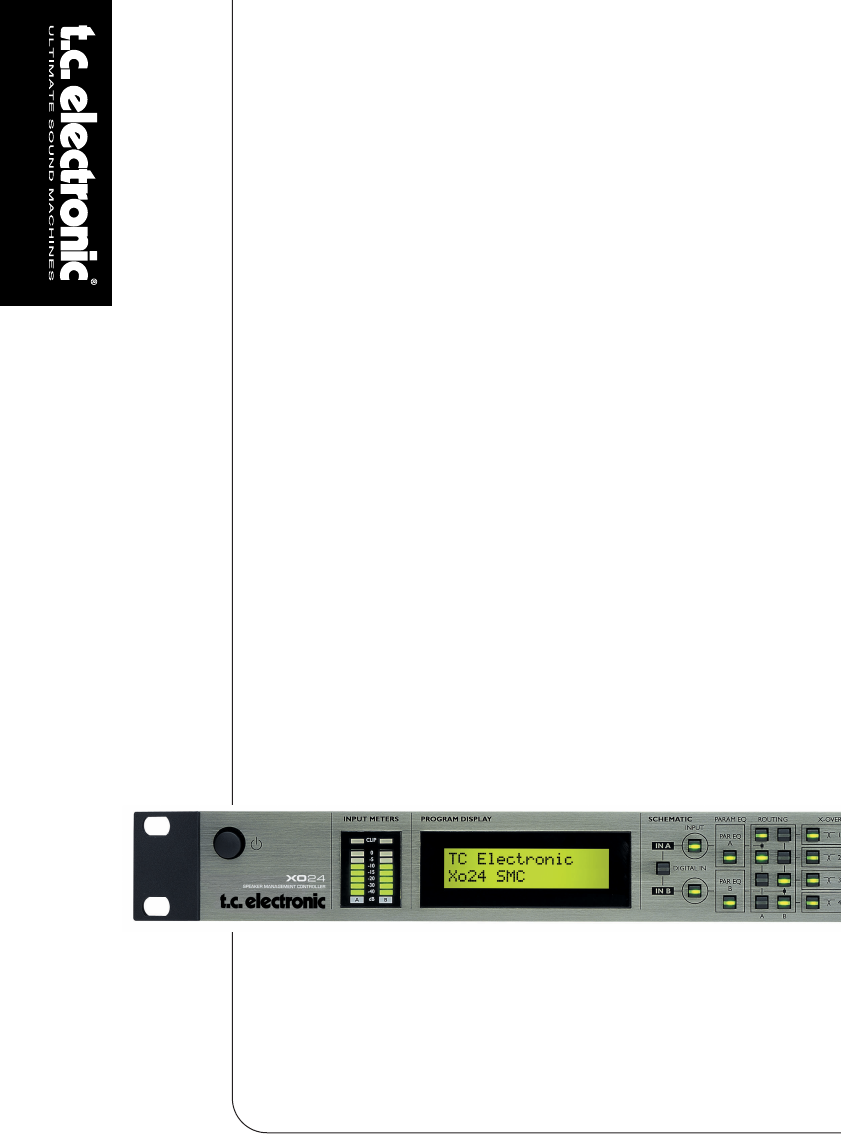
XO24 US_3101.qxd 31-01-2005 10:59 Page 6 FRONT PANEL OVERVIEW POWER On/Off The XO24 uses a switchmode power-supply that accepts from 100-240V AC. INPUT METERS For optimal performance the Input level indication should be around -5dB and occasionally peak at 0dB. If the CLIP indicator is lit the Input signal is too hot. Input sensitivity can be set in the Level menus accessed via the INPUT A/B keys, or via the Setup menu. DISPLAY 32 character LCD displaying various operating parameters.
XO24 US_3101.qxd 31-01-2005 10:59 Page 7 FRONT PANEL OVERVIEW Input A Input B OUTPUT On/Off keys on the Output for each of the four channels. In Edit mode these keys give access to edit the Output level parameter. RECALL In Recall mode you select which preset to recall using the ADJUST encoder and press ENTER to confirm. STORE Press to STORE. Select a storing location using the ADJUST wheel and press ENTER to confirm. ENTER The ENTER key is used to confirm various operations such as Store and Recall.
XO24 US_3101.qxd 31-01-2005 10:59 Page 8 REAR PANEL Balanced Inputs on XLR for channels A/B. Use channel A for mono Input. 8 Balanced Outputs 1-4 on XLR. Digital S/PDIF In and Thru on RCA phono. Com port for data transfer. NO user application. Power Input. The internal switchmode powersupply accepts from 100 to 240 VAC.
XO24 US_3101.
XO24 US_3101.qxd 31-01-2005 10:59 Page 10 TYPICAL SETUPS Stereo Setup - with subs This is a typical stereo setup with a set of subs. Analog: • Input signal is fed on Inputs A/B. • Configure Routing section as illustrated below. • Output channels 1 and 2 feed the front loudspeakers. • Output channels 3 and 4 feed the subs. Configuration overview Using the Digital Input • Digital Input 44.1 or 48kHz must be present in the Digital Input.
XO24 US_3101.qxd 31-01-2005 10:59 Page 11 TYPICAL SETUPS Stereo Setup This setup is a typical small 2-way system. Analog • Input signal is fed to Inputs A and B. • Configure Routing section as illustrated below. • Output channels 1 and 2 feed loudspeaker set A. • Output channels 3 and 4 feed loudspeaker set B. Configuration overview Using the Digital Input • Digital Input 44.1 or 48kHz must be present in the Digital Input.
XO24 US_3101.qxd 31-01-2005 10:59 Page 12 SETUPS 3/4 way setup - Bi-Amp Mid/High This example shows how 2 XO24s can be used in conjunction to distribute Input signals to a 3 or 4 way system per side. For each side: • Source signal can be connected to either Inputs A or B as only one Input per side is used. For this example - use Input A on both controllers. • Configure the Routing section as illustrated below. • Set Crossovers and additional parameters.
XO24 US_3101.qxd 31-01-2005 10:59 Page 13 SETUPS System Distribution - with delay Configuration overview This example is similar to the previous example. However, the idea here is to distribute the signal with delay settings corresponding to the positioning of the speakers. For each side: • Source signal can be connected to either Inputs A or B as only one Input per side is used. For this example - use Input A on both controllers.
XO24 US_3101.qxd 31-01-2005 10:59 Page 14 SETUPS Dual Source Mono - Dual Zone This setup is used where two different zones or rooms need to be covered. In this case Stereo is not the object. • Source 1 is connected to Input A and Source 2 to Input B. • Configure the Routing section as illustrated below. • Set Crossovers and additional parameters. Configuration overview Using the Digital Input • Digital Input 44.1 or 48kHz must be present in the Digital Input.
XO24 US_3101.qxd 31-01-2005 10:59 Page 15 CONTROL SECTION 4 Now you may; - either press ENTER again to confirm and end the store operation - or dial in a preset name of your choice using the CURSOR keys and ADJUST encoder and then press ENTER. 5 The display indicates “Preset Stored” for a successful store operation. The Setup menu Editing Parameters Parameters in the Edit mode: • Press EDIT followed by the key corresponding to the block you wish to edit.
XO24 US_3101.qxd 31-01-2005 10:59 Page 16 FRONT PANEL OPERATION Auto Lock Range: Off, 10 seconds, 30 seconds, 60 seconds Lock Code Range: 0000-9999 “0000” is “no lock code” and the front panel keys can be locked/unlocked simply by using the LOCK key. The following section takes a look at the processing chain following the front panel layout from left to right. On the front panel this is called the “Schematic Section” Digital In Input Bypass A/B - Input Trim The XO24 accepts digital Input at 44.
XO24 US_3101.qxd 31-01-2005 10:59 Page 17 FRONT PANEL OPERATION Routing Routing section -as illustrated on the Front panel The Routing section is the “railway-station” in the signal chain. The signal present on Inputs A/B can via the 2x4 select switches be routed to none, any or all of the four Output channels. From the Routing section out the four channels are individually processed with separate XOver, EQ, Delay, Limiter and Output blocks.
XO24 US_3101.qxd 31-01-2005 11:00 Page 18 FRONT PANEL OPERATION Parametric EQ (Speaker EQ) EQ 1-4 Gain Freq: Width/Slope: Hi Pass or Par EQ ±18 dB 20 Hz – 20 kHz 2nd order ±18 dB 20 Hz – 20 kHz 0,03 – 4 Oct Band 2 Par EQ ±18 dB 20 Hz – 20 kHz 0,03 – 4 Oct Band 3 Par EQ ±18 dB 20 Hz – 20 kHz 0,03 – 4 Oct ±18 dB 20 Hz – 20 kHz 2nd order ±18 dB 20 Hz – 20 kHz 0,03 – 4 Oct Band 1 Band 4 Type: Lo Pass or Par EQ Delay Line Delay for each speaker Line.
XO24 US_3101.qxd 31-01-2005 11:00 Page 19 APPENDIX - TECHNICAL SPECIFICATIONS Analog Inputs Connectors: Impedance, Bal / Unbal: Max. / Min. Input Level @ 0 dBFS: Sensitivity Range @ 12 dB headroom: A to D Conversion: A to D Delay: Dynamic Range: THD: Frequency Response: Crosstalk: XLR 21 kOhm / 13 kOhm +24 dBu / 0 dBu -12 dBu to +12 dBu 24 bit, 128 x oversampling bitstream 0.70 ms / 0.65 ms @ 44.1 kHz / 48 kHz typ < -110 dB, 22 Hz to 22 kHz typ < -110 dB @ 1 kHz, -1 dBFS +0/-0.
20 2 way 2 way 2 way 2 way 2 way 2 way 2 way 2 way #1 #2 #3 #4 #5 #6 #7 #8 Type FullR+Sub200 FullR+Sub100 HiPack+Sub200 A-On B-On A-On B-On A-On B-On A-On B-On B:On/ no EQ A:On/ no EQ B:On/ no EQ A:On/ no EQ A:On/ no EQ B:On/ no EQ A:On/ no EQ B:On/ no EQ A:On/ no EQ B:On/ no EQ A:On/ no EQ B:On/ no EQ A:On/ no EQ B:On/ no EQ A:On/ no EQ B:On/ no EQ A - 1 L-FullRange HiPack A - 2 L-Sub B - 3 R-FullRange HiPack B - 4 R-Sub A - 1 L-FullRange HiPack A - 2 L-Sub B - 3 R-FullR
4 Way 1way #10 #11 TrueByPassSt A:On/ no EQ B:On/ no EQ A:off B:off A-On B-On A:On/ no EQ B:On/ no EQ A:On/ no EQ B:On/ no EQ A-On B-off A-On B-off A-On B-On Input PARAM EQ button INPUT 1 2 3 4 FullRange FullRange FullRange FullRange A - 1 FullRange A - 2 FullRange B - 3 FullRange B - 4 FullRange AAAA- A - 4 Sub A - 3 Lo-Mid A - 1 High A - 2 Hi-Mid A - 3 Sub 18 B - Fullrange A - 1 High 2 A - 2 Mid 15 Routing HP/LP HP/LP HP/LP HP/LP - HP/LP HP/LP HP/LP HP/LP Off Off Off Off Off Off