
User Manual


26 PERFORM-VE User Manual
Appendix A: How it Works: LPF/HPF Filter
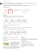
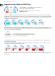
Each lter has a passband, or band of frequencies it will pass at full gain. The LowPass lter (LPF, shown in red) only lets low frequencies pass, while the HighPass
lter (HPF, shown in cyan) only lets high frequencies pass. Both lters each have a cuto frequency that denes where their respective passband ends or begins (LPF &
HPF respectively). On the left side of the ring, Filter Mod sweeps the cuto frequency of the LPF from 20 Hz all the way up to 20,000 Hz. While this is happening, the
cuto frequency of the HPF stays xed at 20 Hz.
Where the two lter passbands overlap (shown in white) is the passband of the LPF/HPF combination - all frequencies in this band make it through, while the rest are
ltered out by either the LowPass lter or the HighPass lter. You can see how the white band gets progressively wider, allowing increasingly high frequency content
to pass as you rotate the knob up to the middle LED position.
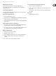
At center LED Filter Mod position, you have the widest passband possible: 20 to 20,000 Hz. You won’t hear any ltering at this setting, since all your audio frequency
content will make it through unchanged.
On the right side of the ring, Filter Mod sweeps the cuto frequency of the HighPass lter (cyan) from 20 Hz all the way up to 20,000 Hz. On this side of the ring, the
cuto frequency of the LowPass lter (red) remains xed at 20,000 Hz.
Now you can see the combined passband (white) gets progressively narrower as your rotate the knob to maximum, preventing increasingly higher frequencies from
passing through.
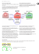
When the LPF/HPF Style is active, Filter Mod controls the cuto frequency of
either the LowPass or HighPass lter (LPF and HPF).
The overlap of these two lters’ frequency response creates a sweeping
BandPass lter (BPF) eect.
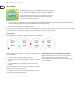
At center LED Filter Mod position, you have the widest passband possible:
20 to 20,000 Hz. You won’t hear any ltering at this setting, since all your audio
frequency content will make it through unchanged.