Active Harmonic Filter Quick Start Unit Software Setup TCI, LLC W132 N10611 Grant Drive Germantown, Wisconsin 53022 Phone: 414-357-4480 Fax: 414-357-4484 Helpline: 800-TCI-8282 Web Site: http://www.transcoil.
No part of this publication may be reproduced, stored in a retrieval system, or transmitted in any form or by any means, mechanical, electronic, photocopying, recording, or otherwise, without the prior written permission of TCI, LLC. The information in this manual is subject to change without notice. Every precaution has been taken in the preparation of this manual. TCI, LLC assumes no responsibility for errors or omissions.
Warning ! Warning ! Warning ! Warning Be sure to read, understand, and follow all safety instructions. Only qualified electricians should carry out all electrical installation and maintenance work on the HarmonicGuard Active Filter (HGA). All wiring must be in accordance with the National Electrical Code (NEC) and/or any other codes that apply to the installation site. Disconnect all power before working on the equipment. Do not attempt any work on a powered Active Harmonic Filter.
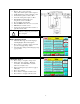
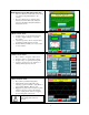
1) Verify unit external connections • Phase A, B, C power connection, with positive A-B-C phase rotation expected • CT H1 Terminal is pointing toward the source • CT feedback on phases A & C to TB-1 • Leave CT shorting bars in place on TB-1 • With the HGA circuit breaker open, energize the source to the HGA • Close the HGA circuit breaker • Fans and HMI should come on in < 5 seconds • HMI will start on Home screen • Load(s) have an integral 5% line reactance or equivalent dc bus choke Warning ! Hazardous
NOTE: Built In Sensor Wiring Error Detection • The active filter has an automatic sensor wiring error detection algorithm built in to the controls. • If a sensor wiring error is detected please reference the Sensor Error Auto Detection section of the full user manual available at www.transcoil.com.
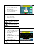
) Converter check – 2 • • • • Press “Setup” to navigate to Setup screen Ensure that “Auto Start En,” “Harmonic Correct En,” and “PWR Fact Correct En” buttons are off (blue color) Press “Status” to navigate to Status screen Press “Run” to start unit operation 7) Remove CT shorting bars • Press “Stop” to turn off unit • Disconnect power from cabinet o Turn off the built in door breaker AND o Turn off the upstream feeder breaker Warning Lethal voltages may be present.
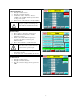
9) Current Polarity – 2 • Navigate to Status screen • Navigate to Line/Load status • Verify that “Volts,” “Current,” “Power,” “I THD," and “V THD” match expected values for the power system • If they do not, verify CTs are correctly installed Warning Improper operation and damage may occur if CTs are installed incorrectly.
TCI, LLC W132 N10611 Germantown, Wisconsin 53022 Phone: 414-357-4480 Fax: 414-357-4484 Helpline: 800-TCI-8282 Web Site: http://www.transcoil.