HarmonicGuard® Series Drive-Applied Harmonic Filter Installation, Operation, and Maintenance Manual TCI, LLC W132 N10611 Grant Drive Germantown, Wisconsin 53022 Phone: 414-357-4480 Fax: 414-357-4484 Helpline: 800-TCI-8282 Web Site: http://www.transcoil.
No part of this publication may be reproduced, stored in a retrieval system, or transmitted in any form or by any means, mechanical, electronic, photocopying, recording, or otherwise, without the prior written permission of TCI, LLC. The information in this manual is subject to change without notice. Every precaution has been taken in the preparation of this manual. TCI, LLC assumes no responsibility for errors or omissions.
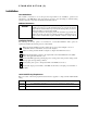
Table of Contents Introduction .............................................................................................................................. 4 Receiving Inspection and Storage............................................................................................ 6 Pre-installation Planning .......................................................................................................... 7 Installation Guidelines ..................................................................
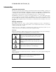
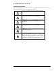
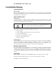
STANDARD OPTION (S) Introduction Safety Instructions Overview This section provides the safety instructions which must be followed when installing, operating, and servicing the HarmonicGuard Passive (HGP) filter. If neglected, physical injury or death may follow, or damage may occur to the filter or equipment connected to the HGP filter. The material in this chapter must be read and understood before attempting any work on, or with, the product.
STANDARD OPTION (S) General Safety Instructions These safety instructions are intended for all work on the HGP. Additional safety instructions are provided at appropriate points on other sections of this manual. Warning Be sure to read, understand, and follow all safety instructions. ! Warning Only qualified electricians should carry out all electrical installation and maintenance work on the HGP filter.
STANDARD OPTION (S) Receiving Inspection and Storage Thank you for selecting the HarmonicGuard Passive (HGP) filter. TCI has produced this filter for use in many variable frequency drive (VFD) applications that require input power line harmonic current reduction. This manual describes how to install, operate and maintain the HGP filter. Receiving Inspection The HGP filter has been thoroughly inspected and functionally tested at the factory and carefully packaged for shipment.
STANDARD OPTION (S) Pre-installation Planning Verify the Application HGP Ratings Make sure that the HGP filter is correct for the application. The voltage ratings of the filter must match the input voltage rating of the connected drive. The horsepower and current ratings of the filter must be appropriate for the connected load. Select a Suitable Location Environment Locating the HGP in a suitable environment will help ensure proper performance and a normal operating life.
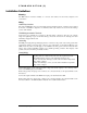
STANDARD OPTION (S) Installation Guidelines Mounting The HGP must be mounted vertically on a smooth, solid surface, free from heat, dampness, and condensation. Wiring Cable Entry Locations The enclosed HGP filters are not provided with enclosure wiring knockouts. A location can be selected at the time of installation. Typical or recommended cable entry locations are shown in the drawings section of this manual.
STANDARD OPTION (S) HGP Filter Operation Caution Thoroughly check the installation before applying power and operating the equipment for the first time. Before Applying Power for the First Time Inspect the installation to make sure that all equipment has been completely and correctly installed in accordance with the Installation Guidelines section of this manual. ♦ Check to see that the cooling fan(s) are operating in units so equipped.
STANDARD OPTION (S) Installation Intended Audience This manual is intended for use by all personnel responsible for the installation, operation and maintenance of the HGP filters. Such personnel are expected to have knowledge of electrical wiring practices, electronic components and electrical schematic symbols. Additional Information Caution This manual provides general information describing your HGP filter.
STANDARD OPTION (S) Maintenance and Service HGP Filter Reliability and Service Life The HGP has been designed to provide a service life that equals or exceeds the life of the VFD. It has been thoroughly tested at the factory to assure that it will perform reliably from the time it is put into service. It is recommended that the following maintenance be done once a year to ensure that the HGP filter will always perform reliably and provide the expected service life.
STANDARD OPTION (S) Fuse Specifications Table 1a lists the specifications for the fuses in the HGP. Refer also to the drawings and other information shipped with the unit. Table 1a – Fuse Specifications for HGP 480 Volt Models HG7 Rating (HP) kVar 5 7.5 10 15 20 25 30 40 50 60 75 100 125 150 200 250 300 350 1.
STANDARD OPTION (S) Product Description HGP Drive-Applied Filter The HGP is a drive-applied harmonic filter designed and developed by TCI to reduce the harmonic currents drawn from the power source by VFDs. It is suitable for use with 3-phase diode bridge rectifier loads such as PWM AC drives. SCR or thyristor loads such as DC drives would require a different filter configuration outside the scope of this product offering. Please contact TCI Technical Support for additional information.
STANDARD OPTION (S) Part Number Encoding Figure identifies the significance of each character in the HGP part number. The example part number, HGP0150AW1S0000 designates an HGP filter that is rated 150 HP, 480 volts, 60 Hz. It includes a line reactor, tuning reactor, and capacitors in a UL Type 1 enclosure. It is designed for use with a 150 HP drive.
STANDARD OPTION (S) Product Technical Specifications Tables 1 & 2 list the major technical specifications for the HGP Filter. Table 1 – HGP Technical Specifications Voltage ratings 480V, 3 phase, 60 Hz kVar ratings 1.3 to 270 kVar depending on voltage. Load types 3-phase diode bridge rectifier loads such as PWM AC drives Load power range 5 -900 HP The included series reactors can tolerate 200% of rated current for at Current ratings least 3 minutes. SCCR (short circuit current Standard rating is 100kA.
STANDARD OPTION (S) Standard Option (S) The Standard Option includes high quality harmonic-grade capacitors and line reactors. This filter will meet the majority of application requirements found today. This cost effective product is available as an open panel version, in a UL Type 1 enclosure, or in an UL Type 3R enclosure. The open panel is perfect for inclusion in a MCC section or easy installation into industry standard enclosures.
CONTACTOR OPTION (C) Contactor Option (C) The Contactor Option includes a contactor, control power transformer and connection terminals in the filter circuit which allows the VFD user to control the insertion of this circuit through the use of a relay contact in the VFD. It is recommended that the VFD contact be programmed to open the contactor below 33% motor power. For variable torque (fan) loads this will be approximately below 70% speed, so the at-speed contact may be used.
FUSE MONITOR WITH CONTACTOR OPTION (F) Fuse Monitor with Contactor Option (F) The Fuse Monitor with Contactor Option includes a voltage monitor module and relay that can be connected to a VFD or other device. The fuse monitor will indicate a fuse failure and communicate this condition through the relay to a connected device.
FUSE MONITOR WITHOUT CONTACTOR OPTION (G) Fuse Monitor without Contactor Option (G) The Fuse Monitor without Contactor Option includes a voltage monitor module and relay that can be connected to a VFD or other device. The fuse monitor will indicate a fuse failure and communicate this condition through the relay to a connected device.
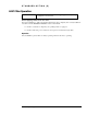
FITLER AND FUSE MONITOR OPERATION Filter and Fuse Monitor Operation HGP Filter Overview The Harmonic Guard Passive (HGP) Filter provides a low impedance path for the major harmonic currents demanded by Variable Frequency Drives (VFDs). This greatly reduces the amount of harmonic currents flowing through the electrical power distribution system, bringing those harmonic currents in line with the IEEE-519 standard for harmonic distortion mandated by an increasing number of utilities.
FITLER AND FUSE MONITOR OPERATION Fuse Monitor Operation and Relay Specifications The fuse monitor relay contact is a single pole, double throw (SPDT) dry type contact. Terminal Block connection TBa-7 is the common connection, TBa-6 is the Normally Closed (NC) connection, and TBa-8 is the Normally Open (NO) Connection.
CP KIT OPTION (0) CP Kit Enclosure (8) with Option (0) The HGP CP Kit Option is a harmonic filter component package designed and developed by TCI to allow qualified customers to build harmonic filters to reduce the harmonic currents drawn from the power source by VFDs. The HGP CP Option is available for 480 volt systems (60 Hz). When properly designed, assembled, and installed, the completed product is intended to be suitable for use with 3-phase diode bridge rectifier loads such as PWM AC VFDs.
CP KIT OPTION (0) Line Reactor Installation Review all Pre-Installation and Installation instructions at the beginning of this manual. If you are assembling a CP unit in your own enclosure, you must provide an enclosure that is adequately sized and ventilated sufficiently to prevent overheating. The maximum temperature of the air around the HGP filter capacitors should not exceed 50°C (122°F).
CP KIT OPTION (0) Table 1a – Fuse Specifications for HGP 480 Volt Models HG7 Rating (HP) kVar 5 7.5 10 15 20 25 30 40 50 60 75 100 125 150 200 250 300 350 1.3 3 3 5 6 8 10 15 15 20 25 30 40 45 60 75 90 105 Max Branch Circuit Fuse Max Line Fusing (J or T) (J, T or L) 20 20 20 30 30 30 30 30 30 50 50 60 80 100 125 150 175 200 30 30 30 30 60 60 60 60 80 100 125 150 200 225 300 375 450 500 NOTE: Customers must provide line fusing to complete SCCR 100KA rating.
VOLTAGE DISTORTION OPTION (0) Typical Voltage Distortion Option (0) The Typical Voltage Distortion Option, intended for applications with levels of background voltage distortion less than 2%, is a configuration that enables the HGP filter to achieve lower levels of current harmonic distortion in applications with low background voltage distortion. This performance option is available in all of the package options.
HIGH VOLTAGE DISTORTION OPTION (1) High Voltage Distortion Option (1) The High Voltage Distortion Option, intended for applications with levels of background voltage distortion of 2% or higher, is a configuration that enables the HGP filter to achieve lower levels of current harmonic distortion in applications with high background voltage distortion. This performance option is available in all of the package options.
TCI, LLC W132 N10611 Grant Drive Germantown, Wisconsin 53022 Phone: 414-357-4480 Fax: 414-357-4484 Helpline: 800-TCI-8282 Web Site: http://www.transcoil.