
User's Manual
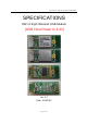

Specifications of 802.11 b/g/n Wireless USB Module
Page 8 of 12
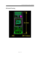
Antenna Connector
Connector Vendor Part#
Antenna*1 Hirose On Board PCB Antenna
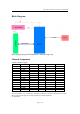
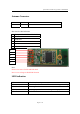
Host Interface Pin Definition
1 FAA pin: WLAN RF Disable/Enable
2 Vcc
3 USB Data-
4 USB Data +
5 GND
6 WLAN LED LINK
Note:
Pin 6 is Low active for WLAN LED Link.
Pin 1 is Low voltage to disable RF function
LED Indication
LED status WLAN card activity
LED on Associated, and authenticated but not transmitting or receiving
LED Slow Blink Scanning for AP
LED Intermittent Blink Activity proportional to transmitting/receiving speed
LED off Radio off
6
5
4
3
2
1