
User's Manual

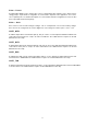


Table Of Contents
- 1 Ordering Information
- 2 Block Diagram and Descriptions
- 3 Electrical Characteristics
- 4 WT32 Pin Description
- 5 Power Control
- 6 Serial Interfaces
- 7 Audio Interfaces
- 8 I/O Parallel Ports
- 9 Software Stacks
- 10 Enhanced Data Rate
- 11 Layout and Soldering Considerations
- 12 WT32 Physical Dimensions
- 13 Package
- 15 RoHS Statement with a List of Banned Materials
- 16 Contact Information

10
4 TBM–CBC5 Pin Description
Figure 2 : TBM–CBC5 connect ion diagram
( top view)
NOTE: VREG_ENA pin is only available with the production version of the module. With engineering
samples the VREG_ENA is internally connected to VDD_BAT.
4.1 Device Terminal Functions
DGN D
Connect digital GND pins to the ground plane of the PCB.
VD D _ I O
Supply voltage connection for the digital I/Os of the module. Supply voltage at this pin can vary between
1.8 V and 3.3 V. Output voltage swing at the digital terminals ofTBM–CBC5 2 is 0 to VDD_IO.
VD D _ BAT
Input for an internal 1.8 V switched mode regulator combined with output of the internal battery charger.
See chapter 5.3 for detailed description for the charger. When not powered from a battery, VDD_IO and
VDD_BAT can be combined to a single 3.3 V supply voltage.
VREG_ EN A
Enable pin for the internal 1,8 V regulator. This pin is only available with production version. With the
engineering samples VREG_ENA is internally connected to VDD_BAT.
VD D _ CH G
Charger input voltage. The charger will start operating when voltage to this pin is applied. When the
charger is not used, this pin should be left floating. See chapter 5.3 for detailed description of the
RES
The RESET pin is an active high reset and is internally filtered using the internal low frequency clock
oscillator. A reset will be performed between 1.5 and 4.0ms following RESET being active. It is
recommended that RESET be applied for a period greater than 5ms.