
Information


・All specifications are subject to change without notice.
18
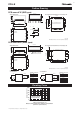
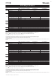
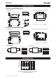
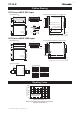
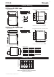
Shape/Dimensions Recommended measurements for mounting board
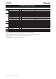
Connection diagram
7.0max.3.0
37.55
25.4
570.6570.6
38.1 32.1
t=0.3
(
4.62
)(
4.62
)
2.54
2.5410.16
2.7
1.0
2.7
0.53.5
0.5
a
b
10
9
8
7
6
5
4
3
2
1
b a
17
16
15
14
13
12
11
ba
17-0.3×0.6
P P P P P P P P
4.47
22.86
27.33
10.16P P P P P
P=2.54
37.55
31.475
6.075
25-ø1.0 (land diameter ø2.0)
Outer shape of product
2-ø1.5 (land diameter ø2.5)
Unit: mm
Allowable tolerance is ±0.5 if not specified separately.
P P P P P P P P
4.47
22.86
27.33
10.16
P
P P P P P
P=2.54
43.0
36.63.2 3.2
1.2
Unit: mm
Allowable tolerance is ±0.5 if not specified separately.
7.5max.
40.9
38.1
32.1
t=0.3
(
4.62
)(
4.62
)
2.54
2.5410.16
10
9
8
7
6
5
4
3
2
1
17
16
15
14
13
12
11
17-0.3×0.6
1.8 1.8
Coplanarity: 0.1 or lower
1
2
3
4
5
6
7
8
9
10
17
16
15
14
13
12
11
+Vout
–Vout
+Vin
–Vin
RC
Terminal connections
No.1 NC No.10 NC
No.2 NC No.11 NC
No.3 RC No.12 +Vout
No.4 NC No.13 +Vout
No.5 NC No.14 +Vout
No.6 +Vin No.15 –Vout
No.7 +Vin No.16 –Vout
No.8 –Vin No.17 NC
No.9 –Vin
Shape/Dimensions Recommended measurements for mounting board
Outer shape of product
Load
CC15-E
Outline Drawing
CC15-xxxxxSF-E (DIP type)
CC15-xxxxxSR-E (SMD type)
a
b
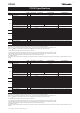
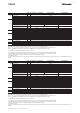
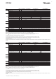
Ambient temperature (°C)
Output power (%)
a:0.5m/s(100LFM)
b:1m/s(200LFM)
Natural air cooling
-40 -20
0
20
40 60 80
100
100
80
60
40
20
0
Output power derating by ambient temperature
(common specification)
Derating Curve