
Data Sheet

TDK-Lambda
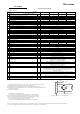
CUS200M
SPECIFICATIONS
CA811-01-01A
MODEL
ITEMS
1 Nominal Output Voltage V 12
Maximum Output Current @ Convection cooling A 16.7
Maximum Output Current @ Forced air cooling (*12) A 16.7
Maximum Output Power @ Convection cooling W 200.4
Maximum Output Power @ Forced air cooling
(*12)
W
200.4
4 Standby Mode Power -
Efficiency @ Convection cooling (Typ.) 115/230 VAC (*1) % 92 / 93
Efficiency @ Forced air cooling (Typ.) 115/230 VAC (*1) % 91 / 93
6 Input Voltage Range (*2) -
Input Current @ Convection cooling (Typ.) 115/230 VAC (*1) A
Input Current @ Forced air cooling (Typ.) 115/230 VAC (*1) A
8 In-rush Current (Typ.) 115/230 VAC (*1)(*3) -
9
-
10 Power Factor (Typ.) 115/230 VAC (*1) -
11 Output Voltage Range V 11.7 ~ 12.6
Maximum Ripple & Noise@ Convection cooling
115/230 VAC(*1)(*4)(*5)
mV 180
Maximum Ripple & Noise@ Forced air cooling
115/230 VAC(*1)(*4)(*5)
mV 180
13 Maximum Line Regulation (*4)(*6) mV 60
14 Maximum Load Regulation (*4)(*7) mV 120
15 Remote Off Power Consumption (*13) -
16 Temperature Coefficient (*4) -
17 Over Current Protection (*8) A >17.5
18 Over Voltage Protection (*9) V 13.2 - 16.2
19 Hold-up time (Typ.) (*1) -
20 Leakage Current (*10) -
21 Remote ON/OFF control -
22 DC-OK
23 Parallel Operation -
24 Series Operation -
25 Operating Temperature (*11) -
26 Operating Humidity -
27 Storage Temperature -
28 Storage Humidity -
29 Cooling (*12) -
31 Isolation Resistance -
33 Shock -
35 EMI (*1) -
36 Immunity -
37 Weight (Typ.) g
38 Size ( L x W x H ) mm
*Read instruction manual carefully, before using the power supply unit.
=NOTES=
*1.Ta=25
℃
, Nominal output voltage and maximum output power.
*2. For cases where conformance to various safety specs (UL, CSA, EN) are required,
input voltage range will be 100 ~ 240VAC (50-60Hz).
Output derating required when Vin is less than 115VAC, refer to output derating curve for details.
*3. Not applicable for the in-rush current to Noise Filter for less than 0.2ms.
*4. Please refer to Fig. A for measurement of Vo, line and load regulation and ripple voltage.
*5. Ripple & noise are measured at 20MHz by using a 150mm twisted pair of load wires terminated with a
0.1uF and 100uF capacitor.
*6. 85~265VAC, constant load.
*7. No load - full load, constant input voltage.
*8. Hiccup with automatic recovery,however power supply may be latched for protection when output is shorted
and manual reset is required (Repower on) .
Avoid to operate at over load or short circuit condition for more than 30 seconds.
*9. OVP circuit shut down the output, manual reset (Repower on) to get output voltage.
*10. Measured by the each measuring method of UL, CSA, and EN (at 60Hz), Ta=25°C.
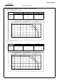
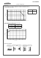
*11. Refer to Output Derating Curve for details of output derating versus
input voltage, ambient temperature and mounting method .
- Load (%) is percent of maximum output power or maximum output current.
Do not exceed its derating of Maximum Load.
- maximum load start up at -40°C is possible. However, it may not fulfill all the specifications.
*12. Forced air cooling with air velocity more than 1.5m/s and air volume more than 15.9CFM (measured at component side, air must flow through component side).
*13. The power consumption refers to input power during remote off and standby 5V is at no load condition.
52.8 - 64.819.8 - 24.3
Less than 196m/s
2
and MIL-STD-810F
Approved by IEC60601-1 2nd Edition and 3rd Edition, EN60601-1 3rd Edition,
ANSI/AAMI ES60601-1, CAN/CSA-C22.2 No.60601-1 3rd Edition(cTUVus),
IEC/EN60950-1 2nd Edition, UL/CSA60950-1 2nd Edition(cTUVus ),
Design to meet GB4943.1
10 - 95%RH (No condensing)
34
Vibration
-
Withstand Voltage
-
-
Safety
90 120
47 ~ 50.4
32
30
240
<0.5W @ 230VAC
16ms @ 200W, 12ms @ 250W
480
-
480
>14.7 > 11 >5.5
Maximum 19.6m/s
2
X,Y,Z 1 hour each
240
Convection or Forced Air Cooling
10 - 95%RH (No condensing)
Possible
26.4 - 32.4
More than 100MΩ at 25°C,70%RH, Output - FG : 500VDC
Input-Output : 4kVAC (20mA) 2x MOPPs
Input-FG : 2kVAC (20mA) 1x MOPP
-40°C - +85°C
Output-FG : 1.5kVAC (20mA) 1xMOPP
Designed to meet IEC61000-4-2 (Level 2,3), IEC61000-4-3 (Level 3),
IEC61000-4-4 (Level 3), IEC61000-4-5 (Level 3,4),
IEC61000-4-6 (Level 3), IEC61000-4-8 (Level 4), IEC61000-4-11
127 x 76.2 x 34 (Refer to Outline Drawing)
Possible
Less than 0.02% / ℃
Possible
0.3mA max @ 265VAC,60Hz
180
350
Designed to meet EN55011-B, EN55022-B, FCC-Class B @ Convection cooling
-20℃- +70℃
At no operating, 10-55Hz (Sweep for 1min.)
92 / 94
92 / 94
201.6
11.2
254.4
23.5 ~ 25.2
92 / 94
252.0
85 - 265 VAC (47-63Hz)
PFHC Built to meet IEC61000-3-2,Class A
201.6
17.6 ~ 18.9
24 48
8.4 4.2
2.2/ 1.1
3.0/ 1.5
5
92 / 94
201.6
92 / 94
5V @ 0.6A(max) at convection cooling, 5V @ 1A(max) at forced air cooling
CUS200M-18CUS200M-12 CUS200M-24 CUS200M-48
18
35A / 70A at Cold Start
200 240 480
240180
12
10.5 5.3
0.99/0.95
2
7
252.0
3
14.0
92 / 94
Output Terminal
Measurement point for Vo Line/Load Regulation
Measurement point for Ripple and Noise
47μ 0.1μ
150mm
Fig.A
A
-V
+V
100 µ
V-
V+