
User manual

16
16
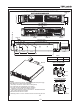
3.7.1 AC Input Connector
3.7.2 AC Input Cord
3.7.3 AC Input Wire Connection
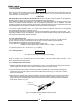
TheAC input connector is a header (Phoenix Contact P/N:PC6-16/4-GF-10, 16) with a screw
plug in connector (Phoenix Contact P/N: PC 6/4-STF-10,16), located on the rear panel.
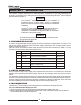
Use suitable wires and tightening torque as follows:
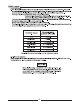
1. Wire diameter: 12AWG for three-phase 200V models and
14AWG for three-phase 400V models. Refer to Table 1-1 for details.
2. Tightening torque: 10.7-13.4Lb-inch. (1.2-1.5Nm).
Refer to section 1.3.4 for details of the recommended AC input cords and to section 3.7 for
disconnected device requirement.
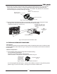
1.Strip the outside insulation of theAC cable approx. 10cm. Trim the wires so that the ground wire is
10mm longer than the other wires. Strip 10mm at the end of each of the wires.
2.Unscrew the base of the strain relief from the helix-shaped body. Insert the base through the
outside opening in theAC input cover and screw the locknut securely (11-14 Lb-inch.) into the
base, from the inside.
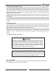
3.Slide the helix-shaped body onto the AC cable. Insert the stripped wires through the strain relief
base until the outer cable jacket is flush with the edge of the base. Tighten (16-18 Lb-inch.) the
body to the base while holding the cable in place. Now the cable is securely fastened inside the
strain relief. Refer to Fig.3-2.
WARNING
AC input cord is not provided with power supply.
WARNING
Some components inside the power supply are at AC voltage even when the On/Off switch is in the
“Off”position. To avoid electric shock hazard, disconnect the line cord and load and wait two
minutes before removing cover.
The power supply ON/OFFswitch is not the main disconnect device and does not completely
disconnect all the circuits from theAC source.
An appropiately rated disconnect device such as circuit breaker, type B plug on power cord, ...etc.,
shall be provided in the final installation. The disconnect device shall comply with UL/IEC 60950-1
requirements and shall be easily accessible.
CAUTION
AC Input Wires No Conductor Pretreatment: Phoenix Contact clamping parts are designed so
that all kinds of copper conductors can be clamped without pretreatment.
It is forbidden to solder the conductors. The solder tin yields and fractures under high pressure. The
result is increased contact resistance and an excessive temperature rise. In addition, corrosion
caused by pickling or fluxes has been observed on soldered conductor ends. Notch fractures at the
transition point from the rigid to the flexible conductor area are also possible.
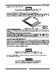
Fig.3-2: Stripped Wires installed in Strain Relief
Screw-on
Locknut