
User manual
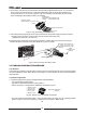


2. Connect the unit to anAC source as described in section 3.7.
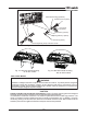
3. Connect a DVM with appropriate cables for the rated voltage to the output terminals.
4. Turn the front panelAC power switch to On.
1. Turn on the output by pressing OUT pushbutton so the OUT LED illuminates.
2. Observe the power supply VOLT display and rotate the Voltage encoder. Ensure that the
output voltage varies while the VOLT encoder is rotated. The minimum control range is from
zero to the maximum rated output for the power supply model.
Compare the DVM reading with the front panel VOLT display to verify the accuracy of the
VOLT display. Ensure that the front panel VOLT LED is on.
3. Turn off the front panelAC power switch.
1. Ensure that the front panelAC power switch is at Off position and the DVM connected to the
output terminals shows zero voltage.
2. Connect a DC shunt across the output terminals. Ensure that the shunt and the wires' current
ratings are higher than the power supply rating. Connect a DVM to the shunt.
3. Turn the front panelAC power switch to On position.
4. Turn on the output by pressing OUT pushbutton so the OUT LED illuminates.
5. Observe the power supply CURRENT display and rotate the CURRENT encoder. Ensure that
the output current varies while the CURRENT encoder is rotated. The minimum control range
is from zero to the maximum rated output for the power supply model.
Compare the DVM reading with the front panel CURRENT display to verify the accuracy of
the CURRENT display. Ensure that the front panel CURRENT LED is on.
6. Turn off the front panelAC power switch.
7. Remove the shunt from the power supply output terminals.
Refer to Section 5.3 for explanation of the OVP function prior to performing the procedure below.
1. Turn the front panelAC power switch to On position and turn on the output by pressing OUT
pushbutton.
2. Using the VOLT encoder, adjust the output voltage to approx. 10% of the unit voltage rating.
3. Momentarily press
the OVP/UVLbutton so that the CURRENT display shows “OUP”. The
VOLTAGE display will show the last setting of the OVP level.
4. Rotate the VOLT encoder CCW to adjust the OVP setting to 50% of the unit voltage rating.
5. Wait a few seconds until the VOLT display returns to show the output voltage.
6. Adjust the output voltage toward it’s maximum and check that the output voltage cannot be
increased more than the OVP setting.
7. Adjust OVP limit to the maximum by repeating step 3 and rotating the VOLT encoder CW.
Refer to Section 5.4 for explanation of the UVLfunction prior to performing the procedure below.
1. Press the OVP/UVL button TWICE so that the CURRENT display shows "UUL". The VOLTAGE
display will show the last setting of the UVL level.
2. Rotate the VOLT encoder to adjust the UVL level to approx. 10% of the unit voltage rating.
3. Wait a few seconds until the VOLT display returns to show the output voltage.
4. Adjust the output voltage toward it’s minimum and check that the output voltage cannot be
decreased below the UVL setting.
5. Adjust the UVL limit to the minimum by repeating step1 and rotating the VOLT encoder CCW.
3.8.3 Constant Voltage Check
3.8.4 Constant Current Check
3.8.5 OVP Check
3.8.6 UVL Check
17
17