
Instructions

22
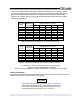
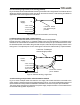
The 80V to 600V models have a four terminal wire clamp output connector. The two left
terminals are the positive outputs and the other two right terminals are the negative outputs.
Max. 30A per terminal.
The connector requirements are as follows:
1. Wires: AWG18 to AWG10.
2. Tightening torque: 4.4-5.3Lb-inch. (0.5-0.6Nm).
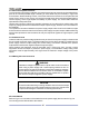
Follow the below instructions for connection of the load wires to the power supply:
1. Strip approx.10mm at the end of each of the wires.
2. Loosen the connector terminal screws.
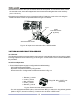
3. Insert the stripped wires into the terminal and tighten the terminal screw securely(see Fig.3-7)
Fig.3-7: Load wires connection to the output connector
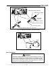
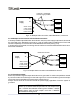
4. Loosen the two chassis screws marked “A” halfway as shown in Fig.3-8.
5. Assemble the protective shield to the chassis and tighten the two screws to fix the shield to
the chassis(see Fig.3-8). Screws tightening torque: 4.8-5.3 Lb-inch.
Fig.3-8: Shield assembly
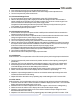
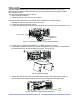
Fig.3-9: Protective shield and wires assembly
6. Tighten the wires to one of the shield sides using ty-wrap or equivalent. Refer to Fig.3-9.
Ensure that the wire length inside the shield is long enough to provide strain relief.
Load
wires
A
A
Load wires
Negative (-)
Output/Return
Positive output (+)
+V
-V