Programmable DC Power Supplies 750W/1500W in 1U Built in RS-232 & RS-485 Interface Advanced Parallel Operation Optional Interface: Compliant LAN IEEE488.
TM GENESYS GEN 750W/1500W SERIES POWER SUPPLIES TM GENESYS USER MANUAL GEN 750W/1500W SERIES POWER SUPPLIES USER MANUAL This Manual Covers Models: GEN12.5-120 GEN40-19 GEN6-100 GEN20-38 GEN40-38 GEN6-200 GEN20-76 GEN50-30 GEN8-90 Covers Models: GEN30-25 GEN60-12.5 GEN8-180This Manual GEN30-50 GEN60-25 GEN12.5-60 GEN12.5-120 GEN40-19 GEN6-100 GEN20-38 GEN40-38 GEN6-200 GEN150-10 GEN80-9.5 GEN20-76 GEN50-30 GEN8-90GEN80-19 GEN300-2.5 GEN30-25 GEN60-12.5 GEN8-180 GEN300-5 GEN100-7.
TABLE OF CONTENTS WARRANTY ..........................................................................................................................................Pg.1 SAFETY INSTRUCTIONS..................................................................................................................... Pg.2 GERMAN SAFETY INSTRUCTIONS ................................................................................................... Pg.4 CHAPTER 1 GENERAL INFORMATION ......................................
TABLE OF CONTENTS 3.9 CONNECTING THE LOAD .......................................................................................................... Pg.18 3.9.1 Load Wiring .......................................................................................................................... Pg.18 3.9.2 Current Carrying Capacity ................................................................................................... Pg.18 3.9.3 Wire termination .................................................
TABLE OF CONTENTS 5.16 DAISY-CHAIN CONNECTION...................................................................................................... Pg.43 5.17 FRONT PANEL LOCKING............................................................................................................. Pg.43 5.17.1 Unlocked front panel ............................................................................................................Pg.43 5.17.2 Locked front panel ..................................................
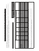
GENESYS, GEN1500W & GEN750W POWER SUPPLY SERIES GENESYS, GEN1500W & GEN750WConcentration POWER SUPPLY ValuesSERIES of Toxic and Hazardous Substances/Elements (wt%) Part Name X O O O O X O O O O O O O O O O O O O O 0.1wt% O O 0.1wt% Mercury (Hg) 0.1wt% O O Mercury (Hg) Lead (Pb) 0.1wt% Lead (Pb) O O O O O O O O O O 0.01wt% O O Cadmium (Cd) 0.01wt% O O O O O O O O O O 0.1wt% O O Hexavalent Chromium 0.1wt% (Cr6+) Hexavalent Chromium (Cr6+) O O O O O O O O O O 0.
WARRANTY This Nemic-Lambda product is warranted against defects in materials and workmanship for a period of five years from date of shipment .During the warranty period, Nemic-Lambda will, at it’s option,either repair or replace products which prove to be defective. LIMITATION OF WARRANTY The warranty shall not apply to defects resulting from improper or inadequate usage or maintenanceby the buyer, buyer supplied products or interfacing.
REGULATORY NOTICES FCC Notice This device complies with Part 15 of the FCC Rules. Operation is subject to the following two conditions: (1) this device may not cause harmful interference, and (2) this device must accept any interference received, including interference that may cause undesired operation. NOTE: This equipment has been tested and found to comply with the limits for a Class A digital device, pursuant to Part 15 of the FCC Rules.
SAFETY INSTRUCTIONS. ENVIRONMENTAL CONDITIONS The GenesysTM power supply series safety approval applies to the following operating conditions: o o *Indoor use *Ambient temperature: 0 C to 50 C *Maximum relative humidity: 90% (no condensation) *Altitude: up to 3000m *Pollution degree 2 CAUTION Risk of Electrical Shock. ! Instruction manual symbol. The instrument will be marked with this symbol when it is necessary for the user to refer to the instruction manual. Indicates hazardous voltage.
SICHERHEITS-INSTALLATIONS ANWEISUNGEN Vorsicht Vor Anschluss an das Netz ist die Aufstellanleitung wie nachstehend beschrieben zu beachten. Die nachstehenden Sicherheitsanweisungen mussen während aller Phasen des Betriebes, des Services und der Reparatur dieser Ausrustung beachtet werden. Alle notwendigen Bedingungen die sicherstellen, dass die Einrichtung zu keiner Gefahr im Sinne dieser Norm fuhren kann, sind in diesem Handbuch beschrieben.
Anderungen und Bauteileersatz Ersatzteilaustausch - und Anderungen durfen nur von autorisiertem Nemic-Lambda SERVICEPERSONEN durchgefuhrt werden. Fur Reparaturen oder Anderungen ist das Gerät zur NemicLambda Service-Niederlassung zu retournieren. SICHERHEITS-HINWEISE Umweltbedingungen TM Die Genesys -Stromversorgungs-Serie ist gemäss den Sicherheitsabnahmen fur folgende Betriebsbedingungen zugelassen. * Stationäre Einrichtungen in Gebäuden. o * Umgebungstemperaturbereich: 0-50 C.
CHAPTER 1 GENERAL INFORMATION 1.1 USER MANUAL CONTENT This user’s manual contains the operating instructions, installation instructions and specifications of the GenesysTM 1500W and 750W power supply series. The instructions refer to the standard power supplies, including the built-in RS232/485 serial communication. For information related to operation with the optional IEEE programming, refer to User Manual for Power Supply IEEE Programming Interface. 1.2 INTRODUCTION 1.2.
* Parallel operation (Master/Slave) with Active current sharing. * Remote sensing to compensate for voltage drop of power leads. * External Analog Programming and Monitoring standard (0-5V or 0-10V, user selectable). * Cooling fan speed control for low noise and extended fan life. * Zero stacking- no ventillation holes at the top and bottom surface of the power supply. * Optional GPIB interface (SCPI compatible). * Optional Isolated Analog programming/monitoring (0-5V or 0-10V, user selectable and 4-20mA).
1.2.9 Cooling and mechanical construction TM The Genesys series is cooled by internal fans. At the installation, care must be taken to allow free air flow into the power supply via the front panel and out of the power supply via the rear panel. The GenesysTM power supplies have a compact and lightweight package which allows easy installation and space saving in the application equipment. CAUTION Observe all torque guidelines within this manual. Over torqueing may damage unit or accessories.
9
UL 60950-1:2007(Ed.2), IEC 60950-1:2005(Ed.2), EN 60950-1:2006(Ed.
NOTES: *1: Minimum voltage is guaranteed to maximum 0.2% of the rated output voltage. *2: Minimum current is guaranteed to maximum 0.4% of the rated output current. *3: For cases where conformance to various safety standards (UL, IEC etc.) is required, to be described as 100-240Vac (50/60Hz). *4: At 100/200V input voltage and maximum output power. *5: From 85~132Vac or 170~265Vac, constant load. *6: From No-load to Full-load, constant input voltage. Measured at the sensing point in Remote Sense.
TM 43.6+/-0.3mm 2.13 GENESYS 750W & 1500W POWER SUPPLIES OUTLINE DRAWINGS Note 7 0-8V 0-300A 24.5 GEN8-300 TDI -Lambda 482.8+/-1.0mm 422.8+/-1.0mm ON OFF Note 5 Note 4 J3 J1 J2 SW1 OUT Note 1 IN AC INPUT Note 2 (80V~600V) 595.3+/-1.0mm 497.8+/-1.0mm Note 3 57.8+/-0.5 A 92.0+/-0.5 A 92.0+/-0.5 21.0 A 432.8+/-1.0mm Note 2 Bus-Bar Detail 6V to 60V Models NOTES: 1.Mating plug supplied with power supply. 2.Bus-bars for 6V to 60V models. See detail.
CHAPTER 3 INSTALLATION 3.1 GENERAL This chapter contains instructions for initial inspection, preparation for use and repackaging for TM shipment. Connection to PC, setting the communication port and linking Genesys power supplies are described in Chapter 7. NOTE TM Genesys power supplies generate magnetic fields which might affect the operation of other instruments. If your equipment is susceptible to magnetic fields, do not position it adjacent to the power supply. 3.
3.4.2 Rack Mount Slides (optional): CAUTION Ensure that the screws used to attach the slides to the unit do not penetrate more than 6mm into the sides of the unit. Use rack mount slides: General Devices P/N: CC3001-00-S160 (ordering P/N: C-300-S-116-RHLH) or equivalent to install the unit in a standard 19” equipment rack. Refer to Fig. 3-1 for slides assembly instructions. Use three #10-32x0.38"(max.) screws at each side. To prevent internal damage, use the specified screw length only.
WARNING Some components inside the power supply are at AC voltage even when the On/Off switch is in the “Off” position. To avoid electric shock hazard, disconnect the line cord and load and wait two minutes before removing cover. CAUTION AC Input Wires No Conductor Pretreatment: Phoenix Contact clamping parts are designed so that all kinds of copper conductors can be clamped without pretreatment. It is forbidden to solder the conductors. The solder tin yields and fractures under high pressure.
4.Route the AC wires to the input connector terminals as required. To connect the wires, loosen the terminal screw, insert the stripped wire into the terminal and tighten the screw securely (4.4-5.3 Lb-inch.). 5.Route the wires inside the cover to prevent pinching. Fasten the cover to the unit using the M3x8 Flat Head screws are provided. Strain relief cover could be opened for inspection. Refer to Fig.3-3 for details. Removable cover. Remove only to inspect AC input wires connection.
2. Connect the unit to an AC source as described in section 3.7. 3. Connect a DVM with appropriate cables for the rated voltage to the output terminals. 4. Turn the front panel AC power switch to On. 3.8.3 Constant Voltage Check 1. Turn on the output by pressing OUT pushbutton so the OUT LED illuminates. 2. Observe the power supply VOLT display and rotate the Voltage encoder. Ensure that the output voltage varies while the VOLT encoder is rotated.
3.8.7 Foldback Check WARNING Shorting the output may expose the user to hazardous voltages. Observe proper safety procedures. Refer to Section 5.5 for explanation of the FOLD function prior to performing the procedure below. 1. Ensure that the output voltage is set to approx. 10% of the unit rating. 2. Adjust the CURRENT encoder to set the current limit to approx. 10% of the unit rating. 3. Momentarily press the FOLD button. Ensure that the FOLD LED illuminates. The output voltage remains unchanged. 4.
2. Wire size should be selected to enable voltage drop per lead to be less than 1.0V at the rated current. Although units will compensate for up to 5V in each load wire, it is recommended to minimize the voltage drop (1V typical maximum) to prevent excessive output power consumption from the power supply and poor dynamic response to load changes. Please refer to Tables 3-2 and 3-3 for maximum wire length to limit voltage drop in American and European dimensions respectively.
3.9.4 Noise and Impedance Effects To minimize the noise pickup or radiation, the load wires and remote sense wires should be twistedpairs to the shortest possible length. Shielding of sense leads may be necessary in high noise environments. Where shielding is used, connect the shield to the chassis via a rear panel Ground screw. Even if noise is not a concern, the load and remote sense wires should be twisted-pairs to reduce coupling, which might impact the stability of power supply.
Wire terminal lug (2 places) M8x15 screw (2 places) Flat washer (2 places) Flat washer (2 places) Spring washer (2 places) Hex Nut (2 places) Screws tightening torque: 104-118 Lb-inch. Fig. 3-5: Load wires connection , 6V to 60V models. A A A A Enclosure bottom cover Enclosure top cover C Fix the bus-bars enclosure top cover using the screws marked “A”. Tighten the screws after fixing. Fig. 3-6 Bus-bars cover 6V to 50V Fix the bus-bars enclosure top cover using the screws marked “A”.
The 80V to 600V models have a four terminal wire clamp output connector: Phoenix Contact P/N: FRONT4-H-7.62/4. The two left terminals are the positive outputs and the other two right terminals are the negative outputs. Max. 30A per terminal. The connector requirements are as follows: 1. Wires: AWG18 to AWG10. 2. Tightening torque: 4.4-5.3Lb-inch. (0.5-0.6Nm). Follow the below instructions for connection of the load wires to the power supply: 1. Strip approx.10mm at the end of each of the load wires. 2.
3.9.7 Connecting single loads, local sensing (default). Fig.3-10 shows recommended load and sensing connections for a single load. The local sense lines shown are default connections at the rear panel J2 sense connector. Local sensing is suitable for applications where load regulation is less critical. +V + -V - Load Power Supply - Rem.sense -Local sense Load lines, twisted pair, shortest length possible. +Local sense +Rem.sense Fig.3-10: Single load connection, local sensing 3.9.
Load lines, twisted pair, shortest length possible. +V Power Supply + Load#1 - -V + Load#2 - - Rem.sense -Local sense + Load#3 - +Local sense +Rem.sense Fig.3-12: Multiple loads connection, radial distribution, local sense 3.9.10 Multiple load connection with distribution terminals If remotely located output distribution terminals are used, the power supply output terminals should be connected to the distribution terminals by a pair of twisted and/or shielded wires.
WARNING OUTPUT TERMINAL GROUNDING There is a potential shock hazard at the RS232/485 and the IEEE ports when using power supplies with rated or combined voltage greater than 400V with the Positive Output of the power supplies is grounded. Do not connect the Positive Output to ground when using the RS232/485 or IEEE under the above conditions. 3.10 LOCAL AND REMOTE SENSING The rear panel J2 sense connector is used to configure the power supply for local or remote sensing of the output voltage. Refer to Fig.
3.10.3 Remote sensing WARNING There is a potential shock hazard at the sense point when using power supply with a rated output voltage greater than 40V. Ensure that the connections at the load end are shielded to prevent accidental contact with hazardous voltages. CAUTION When using shielded sense wires, ground the shield in one place only. The location can be the power supply chassis or one of the output terminals. Use remote sense where the load regulation at the load end is critical.
CHAPTER 4 FRONT AND REAR PANEL CONTROLS AND CONNECTORS 4.1 INTRODUCTION TM The Genesys Power Supply series has a full set of controls, indicators and connectors that allow the user to easily setup and operate the unit. Before starting to operate the unit, please read the following sections for explanation of the functions of the controls and connectors terminals. - Section 4.2: Front panel controls and indicators. - Section 4.3: Rear panel controls and connectors. 4.
Table 4-1: Front Panel controls and indicators Number Control/Indicator Description Section 5 4 digit, 7-segment LED display. Normally displays the output current. When the PREV button is pressed, the CURRENT display display indicates the programmed setting of output current. CURRENT indicator Green LED, lights for Constant-Current mode operation. 6 CURRENT control 4 7 OUT button 8 OUT indicator 9 10 11 12 13 14 High resolution rotary encoder for adjusting the Output Current.
Table 4-1: Front Panel controls and indicators Number Control/Indicator Description Green LED, lights when PREV button is pressed. PREV indicator 15 16 Section Voltage and Current Fine/Coarse adjustment control. Operates as a toggle switch. In Fine mode, the VOLTAGE and CURRENT encoders operate with high resolution and in Coarse mode with lower resolution (approx. 6 turns). Auxiliary function: Advanced Parallel Operation Mode setting. Green LED, lights when the unit is in Fine mode.
Table 4-2: Rear panel connections and controls Number Item Description Section 4 Remote Out RJ-45 type connector, used for chaining power supplies to form 7.3 connector a serial communication bus. 7.4 5 Programming and Monitoring connector Connector for remote analog interface. Includes output voltage and 4.5 current limit programming and monitoring signals, Shut-off control (electrical signal), Enable/Disable control (dry-contact), power supply ok (PS_OK) signal and operation mode (CV/CC) signal.
31
4.5 REAR PANEL J1 PROGRAMMING AND MONITORING CONNECTOR The J1 Programming and Monitoring connector is a DB25 subminiature connector located on the power supply rear panel. Refer to Table 4-4 for description of the connector functions. The power supply default configuration is Local operation which does not require connections to J1. For remote operation using J1 signals use the plug provided with power supply or equivalent type.
Fig.4-4: J1 connector terminals and functions Same ground as P/S negative sense (-S) VMON COM CV/CC IF_COM IF_COM ENA_IN IPGM VPGM LOC/ REM 13 25 12 24 11 23 10 22 9 21 8 6 7 20 19 18 5 4 17 3 16 15 2 1 14 Isolated from PS outputs, same ground as RS232/485 P IMON IPGM_RTN VPGM_RTN LOC/REM SIGNAL ENA_OUT SO PS_OK Table 4-4: J1 connector terminals and functions J1 Signal Function contact name Enable /Disable the power supply output by dry-contact J1-1 ENA_IN (short/open) with ENA_OUT.
CHAPTER 5 LOCAL OPERATION 5.1 INTRODUCTION This Chapter describes the operating modes that are not involved in programming and monitoring the power supply via its serial communication port (RS232/RS485) or by remote analog signals. Ensure that the REM/LOC LED on the front panel is Off, indicating Local mode. If the REM/LOC LED is On, press the front panel REM/LOC button to change the operating mode to local. - For information regarding remote analog programming refer to Chapter 6.
- Enabled output, power supply in Constant Voltage mode: Press the PREV button and then rotate the CURRENT encoder knob. The CURRENT meter will show the programmed current limit for 5 seconds after the adjustment has been completed, and then will return to show the actual load current. - Enabled output, power supply in Constant Current mode: Rotate the CURRENT encoder knob to adjust the current limit. 4. Adjustment resolution can be set to Coarse or Fine adjustment.
5.4 UNDER VOLTAGE LIMIT (UVL) The UVL prevents adjustment of the output voltage below a certain limit.The combination of UVL and OVP functions, allow the user to create a protection window for sensitive load circuitry. 5.4.1 Setting the UVL level Setting the UVL can be made when the power supply output is Enabled (On) or Disabled (Off). To set the UVL level, press the OVP/UVL button TWICE, so that the CURRENT meter shows “UUL”. The VOLTAGE meter shows the UVL setting level.
When the unit is shut-off by J1 signal, the VOLTAGE display will show “SO” to indicate the unit state. J1 contact 15 is the SO signal input and contacts 2 and 3, IF_COM, are the signal return (connected internally). Contacts 2,3 and 15 are optically isolated from the power supply output. The SO control logic can be selected by the rear panel SW1 Setup switch. Refer to Table 5-2 for SW1 setting and SO control logic.
5.11 SAFE START AND AUTO-RESTART MODES When turning on the power supply AC On/Off, it can start to its last setting of Output Voltage and Current limit with the output enabled (Auto-restart) or start with the output disabled (Safe mode). Press and hold the OUT button to select between Safe start and Auto-restart modes. The VOLTAGE display will continuously cycle between "SAF" and "AU7” every 3 seconds. Releasing OUT pushbutton while one of the modes is displayed, selects that mode.
CAUTION Do not connect power supplies from different manufacturers in series or in parallel. 5.14.1 Series connection for increased output voltage In this mode, two units are connected so that their outputs are summed. Set the current limit of each power supply to the maximum that the load can handle without damage. It is recommended that diodes be connected in parallel with each unit output to prevent reverse voltage during start up sequence or in case one of the units shuts down.
Programming by external resistor is possible . Refer to section 6-5 for details. The communication port is referenced to the IF_COM which is isolated from the power supply output potential. Therefore power supplies connected in series can be chained using the Remote-In and Remote-Out connectors. Refer to chapter 7 for details. 3. Programming by external resistor: 4. Programming via the Serial Communication port (RS232/RS485): 5.14.
5.15 PARALLEL OPERATION Up to four units of the same VOLTAGE and CURRENT rating can be connected in parallel to provide up to four times the output current capability. One of the units operates as a master and the remaining units are slaves. The slave units are analog programmed by the master unit. In remote digital operation, only the master unit can be programmed by the computer while the slave units may be connected to the computer for voltage, current and status readback only.
2. Setting the units as Master or Slave a) Depress and hold the FINE button for 3 seconds. The Master/Slave configuration will be displayed on the Current Display. Rotate the CURRENT encoder to obtain the desired mode. Refer to Table 5-4 for the CURRENT display and modes of operation.
NOTE NOTE With local sensing it is important to minimize the wire length and resistance. Also the positive and negative wire resistance should be close as possible to each other to achieve current balance between power supplies.
CHAPTER 6 REMOTE ANALOG PROGRAMMING 6.1 INTRODUCTION The rear panel connector J1 allows the user to program the power supply output voltage and current limit with an analog device. J1 also provides monitoring signals for output voltage and output current. The programming range and monitoring signals range can be selected between 0-5V or 0-10V using the setup switch SW1.
6.4 REMOTE VOLTAGE PROGRAMMING OF OUTPUT VOLTAGE AND CURRENT LIMIT CAUTION To maintain the isolation of power supply and prevent ground loops, use an isolated programming source when operating the power supply via remote analog programming at J1 connector. Perform the following procedure to set the power supply to Remote Voltage programming : 1. Turn the power supply AC On/Off switch to Off. 2.
6.5 RESISTIVE PROGRAMMING OF OUTPUT VOLTAGE AND CURRENT LIMIT For resistive programming, internal current sources, for output voltage and/or output current control, supply 1mA current through external programming resistors connected between J1-9 & 22 and J1-10 & 23. The voltage across the programming resistors is used as a programming voltage for the power supply. Resistance of 0~5Kohm or 0~10Kohm can be selected to program the output voltage and current limit from zero to full scale.
6.6 REMOTE MONITORING OF OUTPUT VOLTAGE AND CURRENT The J1 connector, located on the rear panel provides analog signals for monitoring the output voltage and output current. Selection of the voltage range between 0-5V or 0-10V is made by setup switch SW1-4. The monitoring signals represent 0 to 100% of the power supply output voltage and output current.The monitor outputs have 500 ohm series output resistance.
CHAPTER 7 RS232 & RS485 REMOTE CONTROL 7.1 INTRODUCTION TM This chapter describes the operation of the Genesys 750W and 1500W power supplies via the serial communication port. Details of the initial set-up, operation via RS232 or RS485, the command set and the communication protocol are described in this chapter. 7.2 CONFIGURATION 7.2.
2. There are two Remote modes: In this mode, return to local can be made by the front panel REM/LOC or via serial port command RMT 0. Set the unit into Remote mode via serial port RMT 1 command. 1. Remote: 2. Local Lockout: In this mode the unit can be returned to Remote mode via the serial port RMT 1 command or by turning off the AC power until the display turns off and then turn it to on again. In Local Lockout mode, the front panel REM/LOC button is not active.
50
7.4.2 Multi power supply connection to RS232 or RS485 bus Daisy-chain up to 31 units can be connected to RS232 or RS485 bus. The first unit connects to the controller via RS232 or RS485 and the other units are connected with RS485 bus. 1. First unit connection: Refer to section 7.4.1 for connecting the first unit to the controller. 2. Other units connection: The other units on the bus are connected via their RS485 interface. Refer to fig.7-5 for typical connection.
7.5.7 Error message If an error is detected in a command or query, the power supply will respond with an error message. Refer to section 7.6 for details. 7.5.8 Backspace The backspace character (ASCII 8) clears the last character sent to the power supply. 7.6 ERROR MESSAGES The power supply will return error messages for illegal commands and illegal programming parameters. Refer to Table 7-1 for programming error messages and Table 7-2 for commands error messages.
7.7.3 Initialization control commands # 1 2 3 4 5 6 7 Command Description ADR is followed by address which can be 0 to 30 and is used to access the ADR n power supply . Clear status. Sets FEVE and SEVE registers to zero (refer to section 7-8). CLS Reset command.
7.7.5 Output control commands-cont # Command Description MC? Reads the actual output current. Returns 5 digits string. 6 (See Note 2) Example: 200A supply sends 000.50, 110.12, 200.00, etc... Display Voltage and Current data. Data will be returned as a string of ASCII characters. A comma will separate the different fields. The fields, in order, are: Measured Voltage, Programmed Voltage, Measured Current, Programmed Current, Over Voltage Set point and Under Voltage Set Point. Example: 5.9999, 6.0000, 010.
NOTES: 1. In Advanced parallel mode (refer to Sec. 5.15.2), “n” is the total system current. 2. In Advanced parallel mode, “MC?” returns the Master unit current multiplied by the number of slave units+1. 7.7.6 Global output commands 1. General All supplies, even if not the currently addressed supply, receiving a global command will execute the command. No response to the PC issuing the command will be returned to the PC.
GEN750W models Table 7-4: Current programming range Model GEN6-100 GEN8-90 GEN12.5-60 GEN20-38 GEN30-25 GEN40-19 GEN60-12.5 GEN80-9.5 GEN100-7.5 GEN150-5 GEN300-2.5 GEN600-1.3 Minimum (A) 000.00 00.00 00.000 00.000 00.000 00.000 00.000 0.000 0.000 0.000 0.000 0.000 GEN1500W models Table 7-5: Current programming range Maximum (A) 100.00 90.00 60.000 38.000 25.000 19.000 12.500 9.500 7.500 5.000 2.500 1.300 Model GEN6-200 GEN8-180 GEN12.
7.8 STATUS, ERROR AND SRQ REGISTERS 7.8.1 General This section describes the various status error and SRQ registers structure. The registers can be read or set via the RS232/485 commands. When using the IEEE option, refer to the user manual TM for Genesys Power Supply IEEE Programming interface. Refer to Fig.7-7 for the Status and Error Registers Diagram. Command Error (”Cnn”) One response for every command or query received.
7.8.2 Conditional registers Table 7-8: Fault Condition Register BIT Fault name Fault symbol Bit Set condition 0 (LSB) Spare bit SPARE Fixed to zero AC Fail 1 AC AC fail has occurred. OTP OTP shutdown has Over 2 temperature occurred. Foldback shutdown Foldback FOLD 3 has occurred. Bit Reset condition Fixed to zero The AC input returns to normal. The power supply cools down. The supply output is turned On by front panel button or OUT 1 command.
Refer to Tables 7-10 to 7-13 for details of the Enable and Event registers. 1.Fault Enable Register The Fault Enable Register is set to the enable faults SRQs.
3.Status Enable register The Status Enable Register is set by the user to enable SRQs from changes in power supply status. Table 7-12: Status Enable Register BIT Status name 0 (LSB) Constant Voltage Status symbol Bit Set condition CV User command: "SENA nn" is received, where nn is hexadecimal bits. Bit reset condition User command: "SENA nn" is received, where nn is hexadecimal bits. If "nn"=00, no SRQ is sent when there is a change in Status Condition Register.
7.9 SERIAL COMMUNICATION TEST SET-UP Use the following instructions as basic set-up to test the serial communication operation. TM 1.Equipment: PC with Windows Hyper Terminal, private edition, software installed, Genesys power supply, RS232 cable. 2.PC set-up: 2.1 Open Hyper Terminal.......................New Connection. 2.2 Enter a name 2.3 Connect to.......................................Direct to Com1 or Com 2 2.4 Configure port properties: Bits per second .......9600 Data bits ..................
CHAPTER 8 ISOLATED ANALOG PROGRAMMING OPTION 8.1 INTRODUCTION TM Isolated Analog Programming is an internal option card for analog programming of the Genesys power supply series. The option is factory installed and cannot be obtained with GPIB (IEEE) Interface. Output Voltage and Current Limit can be programmed and readback through optically isolated signals which are isolated from all other ground references in the power supply. There are two types of Isolated Analog programming cards: 1.
8.3 ISOLATED PROGRAMMING & MONITORING CONNECTOR Refer to Table 8-1 for detailed description of the rear panel Isolated Programming & Monitoring connector. To provide the lowest noise performance, it is recommended to use shielded-twisted pair wiring. Refer to Fig.8-1 for description of the connector. Isolated programming plug P/N: MC1.5/8-ST-3.81, Phoenix. 1 2 3 4 5 6 7 8 Shield Shield +VPROG_ISO +IPROG_ISO GND +IMON_ISO +VMON_ISO GND Fig.
8.4 SETUP AND OPERATING INSTRUCTIONS CAUTION To prevent damage to the unit, do not program the output voltage and current to higher then the power supply rating. 8.4.1 Setting up the power supply for 0-5/0-10V Isolated Programming and Monitoring Perform the following procedure to configure the power supply: 1. Turn the power supply AC power switch to Off. 2. Connect a short between J1-8 and J1-12 (refer to Table 4-4). 3.
CHAPTER 9 MAINTENANCE 9.1 INTRODUCTION This chapter provides information about maintenance, calibration and troubleshooting. 9.2 UNITS UNDER WARRANTY Units requiring repair during the warranty period should be returned to a Lambda authorized service facility. Refer to the addresses listing on the back cover of this manual. Unauthorized repairs performed by other than the authorized service facilities may void the warranty. 9.
66
USER MANUAL INDEX A ac cables ac fail accessories acknowledge address adjustment auto-restart 8, 15 29 8 51 18, 48 65 38 B back space baud rate bipolar voltage 52 18, 48 40 C calibration configuration checksum communication constant current constant voltage cooling cv indicator cc indicator 65 48 51 51, 61 17, 34 17, 34 8, 10 27, 37 27, 37 D daisy-chain display 43, 51 27 E enable error message external resistor external voltage F fine foldback fuse front panel control front panel locking 33 52 46 4
NOTES 68
NOTES 69
NOTES 70
NOTES 71
NOTES 72
NOTES 73
NOTES 74
UK TDK-Lambda UK Ltd. Kingsley Avenue Ilfracombe, Devon EX 34 8ES United Kingdom Tel: +44-1271-856666 Fax: +44-1271-864894 E-mail: powersolutions@emea.tdk-lambda.com www.uk.tdk-lambda.com FRANCE TDK-Lambda France SAS ZAC des Delaches BP 1077 - Gometz le Chatel 91940 LES ULIS Tel: +33 1 60 12 71 65 Fax: +33 1 60 12 71 66 E-mail: france@fr.tdk-lambda.com www.fr.tdk-lambda.com GERMANY TDK-Lambda Germany GmbH Karl-Bold-Str.40, D-77855 Achern, Germany Tel: +49-7841-666-0 Fax: +49-7841-500-0 E-mail: info.