
Data Sheet

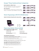

General Specifications Genesys™ 750W/1500W
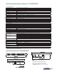
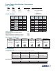
Outline Drawing Genesys™ 750W/1500W Units
|4
NOTE
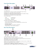
1. Bus bars for 6v to 60v models (shown)
Wire clamp connector for 80V to 600V models
2. Plug connectors included with the power supply
3. Chassis slides mounting holes #10-32 marked "A"
GENERAL DEVICES P/N: C-300-S-116 or equivalent
*1: For cases where conformance to various safety standards (UL, IEC etc.) is required, to be described as 100-240Vac (50/60Hz).
All specifications subject to change without notice.
2.1 INPUT CHARACTERISTICS
1. Input voltage/freq. (*1)
2. Power Factor 0.99 @100/200Vac, rated output power.
3. EN61000-3-2,3 compliance Complies with EN61000-3-2 class A and EN61000-3-3 at 20~100% output power.
4. Input current 100/200Vac
5. Inrush current 100/200Vac
750W :Less than 25A, 1500W :Less than 50A
6. Hold-up time
More than 20mS , 100Vac , at 100% load.
750W :10.5A / 5A, 1500W :21A / 11A
85~265Vac continuous, 47~63Hz, single phase
2.6 MECHANICAL CONSTRUCTION
1. Cooling
2. Dimensions (WxHxD) W: 422.8mm, H: 43.6mm, D: 432.8mm (excluding connectors, encoders, handles, etc.)
3. Weight
750W: 7Kg (15 Lbs) 1500W: 8.5Kg (18 Lbs)
4. AC Input connector 750W: IEC320 AC Inlet.
1500W: Screw terminal block, Phoenix P/N: FRONT-4-H-7.62 , with strain relief
5.Output connectors
6V to 60V models: Bus-bars (hole Ø 8.5mm). 80V to 600V models:
wire clamp connector
, Phoenix P/N: FRONT-4-H-7.62
Forced air flow: from front to rear. No ventilation holes at the top or bottom of the chassis; Variable fan speed.
2.7 RELIABILITY SPECS
1. Warranty 5 years.
1. Parallel Operation
2. Series Operation
Up to 4 units in master/slave mode with single wire current balance connection
Up to 2 units. with external diodes. 600V Max to Chassis ground
2.2 POWER SUPPLY CONFIGURATION
2.3 ENVIRONMENTAL CONDITIONS
1. Operating temp
2. Storage temp
-20~70°C
3. Operating humidity
30~90% RH (non-condensing).
4. Storage humidity
10~95% RH (non-condensing).
5. Vibration
MIL-810E, method 514.4 , test cond. I-3.3.1. The EUT is fixed to the vibrating surface.
6. Shock
Less than 20G , half sine , 11mSec. Unit is unpacked.
7. Altitude
Operating: 10000ft (3000m), Derat output current by 2%/100m abouve 2000m, Non operating: 40000ft (12000m).
0~50 °C, 100% load.
EN55022A, FCC part 15-A, VCCI-A.
2.4 EMC
1.Applicable Standards:
2.ESD
IEC1000-4-2. Air-disch.-8KV, contact disch.-4KV
3.Fast transients
IEC1000-4-4. 2KV
4.Surge immunity
IEC1000-4-5. 1KV line to line, 2KV line to ground
5.Conducted immunity
IEC1000-4-6, 3V
6.Radiated immunity
IEC1000-4-3, 3V/m
7.Conducted emission
EN55022B,FCC part 15J-B, VCCI-B.
8.Radiated emission
EN55022A,FCC part 15-A, VCCI-A.
9.Voltage dips
EN61000-4-11
10. Conducted emission
11. Radiated emission
EN55022B, FCC part 15-B, VCCI-B.
More than 100Mohm at 25°C , 70% RH, 500Vdc
2.5 SAFETY
1.Applicable standards:
400<Vout<600V:Output is hazardous, IEEE/Isolated analog are not SELV.
2.Withstand voltage
60<Vout<600V models: Input-Haz. Output: 2.5KVrms 1min, Input-SELV: 3KVrms 1min.
Hazardous Output.-SELV: 1.9KVrms 1min, Hazardous Output-Ground:1.9KVrms 1min.
3.Insulation resistance
CE Mark, UL60950,EN60950 listed. Vout<60V:Output is SELV , IEEE/Isolated analog are SELV.
60<Vout<400V: Output is hazardous, IEEE/Isolated analog are SELV.
Vout<60V models :Input-Outputs (SELV): 3.0KVrms 1min, Input-Ground: 2.0KVrms 1min.
Input-Ground: 2KVrms 1min.