
Instructions


57
OR
OR
OR
SRQ
Messages
Address
Changed
Response
messages
Command Error (”Cnn”)
Execution Error (”Enn”)
Query Response (”message”)
Command Response (”OK”)
CV
CC
NFLT
FLT
AST
FDE
0
LCL
CV
CC
NFLT
FLT
0
0
0
LCL
0
0
0
OR
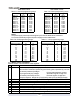
Status Registers
Condition
Enable
Event
Constant Voltage
Constant Current
No Fault
Fault
Auto Start
Fold Enabled
Spare
Local Mode
0
1
2
3
4
5
6
7
“STAT?”
“SENA xx”
“SENA?”
“SEVE?”
0
AC
OTP
FLD
OVP
SO
OFF
ENA
Fault Registers
Condition
Enable
Spare
AC Fail
Over Temperature
Foldback (tripped)
Over Volt Prot
Shut Off (rear panel)
Output Off (front panel)
Enable Open
0
1
2
3
4
5
6
7
“FLT?”
“FENA xx”
“FENA?”
0
AC
OTP
FLD
OVP
SO
OFF
ENA
OR
Event
“FEVE?”
MSB
MSB
LSB
Serial
TXD
LSB
One response for every command
or query received.
One SRQ when SEVE goes
from all zeroes to any bit set.
Setting more SEVE bits does
not cause more SRQs.
Positive Logic:
0 = No Event
1 = Event Occured
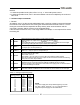
7.8 STATUS, ERROR AND SRQ REGISTERS
This section describes the various status error and SRQ registers structure. The registers can be
read or set via the RS232/485 commands. When using the IEEE option, refer to the user manual
for Genesys Power Supply IEEE Programming interface.
Refer to Fig.7-7 for the Status and Error Registers Diagram.
7.8.1 General
TM
Fig.7-7: Status and Error Registers Diagram
7.8.2 Conditional registers
The fault Condition Register and the Status Condition Register are read only registers that the user
may read to see the condition of the supply. Refer to table 7-8 for description of the Fault Condition
Register bits and Table 7-9 for the Status Condition register bits.
SRQ = “!nn”,
nn = address