
Data Sheet
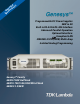


Genesys ™ 5kW Specifications
*1: Minimum voltage is guaranteed to maximum 0.2% of rated output voltage.
*2: Minimum current is guaranteed to maximum 0.4% of rated output current.
*3: For cases where conformance to various safety standards (UL, IEC, etc›) is required, to be
described as 190-240Vac (50/60Hz) for 3-Phase 208V models, and 380~415Vac (50/60Hz) for
3-Phase 400V models.
*4: 3-Phase 208V models: At 208Vac input voltage, 3-Phase 400V: At 380Vac input voltage. With
rated output power.
*5: Not including EMI filter inrush current, less than 0.2mSec.
*6: 3-Phase 208V models: 170~265Vac, constant load. 3-Phase 400V models: 342~460Vac,
constant load.
*7: From No-Load to Full-Load, constant input voltage. Maximum drop in Remote Sense.
*8: For 8V~300V models: Measured with JEITA RC-9131A (1:1) probe.
For 600V model: Measured with 10:1 probe.
*9: From 10% to 90% or 90% to 10% of Rated Output Voltage, with rated, resistive load.
*10:From 90% to 10% of Rated Output Voltage.
*11: For load voltage change, equal to the unit voltage rating, constant input voltage.
*12: For 8V~16V models the ripple is measured from 2V to rated output voltage and rated output
current. For other models, the ripple is measured at 10~100% of rated output voltage and rated
output current.
*13: The Constant Current programming readback and monitoring accuracy does not include the
warm-up and Load regulation thermal drift.
*14: Measured at the sense point.
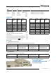
1.0 MODEL
Specifications in Blue are improved
MODEL
GEN 8-600 10-500 16-310 20-250 30-170 40-125 60-85 80-65 100-50 150 -34 200-25 300 -17 400 -13 500 -10
600-8.5
1.Rated output voltage(*1) V 8 10 16 20 30 40 60 80 100 150 200 300 400 500 600
2.Rated Output Current(*2) A 600 500 310 250 170 125 85 65 50 34 25 17 13 10 8.5
3.Rated Output Power W 4800 5000 4960 5000 5100 5000 5100 5200 5000 5100 5000 5100 5200 5000 5100
1.1 CONSTANT VOLTAGE MODE
1.Max.line regulation ( 0.01% of rated Vo )(*6)
mV 0.8 1.0 1.6 2 3 4 6 8 10 15 20 30 40 50 60
2.Max load regulation (0.015% of rated Vo+5mV )(*7)
mV 6.2 6.5 7.4 8 9.5 11 14 17.7 20 27. 5 35 50 65 80 95
3.Ripple and noise p-p 20MHz (*8)
mV 75 75
70
75
70 70 70 80 90
120
200 200
350
300 450
4.Ripple r.m.s 5Hz~1MHz
mV
8 8
10 10 10
8 8
15 15
20
45 60
70 70 100
5.Remote sense compensation/wire V 2 2 2 2 5 5 5 5 5 5 5 5 5 5 5
6.Temp. coefficient
PPM/°C
50PPM/°C
of rated output voltage
,following 30 minutes warm-up
7.Temp. stability 0.01% of rated Vout
over 8hrs interval following 30 minutes warm-up. Constant line, load & temp.
8.Warm-up drift Less than 0.05% of rated output voltage+2mV over 30 minutes following power On.
9.Up-prog. response time, 0~Vo Rated (*9) mS 30 50 65 80 100
10.Down-prog response
time
Full-load (*9) mS 15 50 80 100 135 170 200
No-load (*10) mS 400 500 600 700 800 900 1000 120 0 1500 2000 2000 2500 3000 3000 3000
11.Transient response time mS
Time for output voltage to recover within 0.5% of its rated output for a load change 10-90% of rated output current. Output set-
point: 10-100%, local sense. Less than 1mSec for models up to and including 100V. 2msec for models above 100V
1.2 CONSTANT CURRENT MODE
1.Max.line regulation (0.05% of rated Io)(*6) mA 300 250 155 125 85 62.5 42.5 32.5 25 17 12.5 8.5 6.5 5 4.25
2.Max.load regulation (0.1% of rated Io)(*11) mA 600 500 310 250 170 125 85 65 50 34 25 17 13 10 8.5
3.Ripple r.m.s 5Hz~1MHz . (*12)
mA
1700 1600 1000 700 350 180 120 80 50 50 50 20 15 10 10
4.Load regulation thermal drift Less than 0.1% of rated output current over 30 minutes following load change.
5.Temp. coefficient
PPM/°C
70PPM/ºC from rated output current
, following 30 minutes warm-up.
6.Temp. stability 0.01% of rated Iout
over 8hrs. interval following 30minutes warm-up. Constant line, load & temperature.
7.Warm-up drift
8V~16V models: Less than ±0.5% of rated output current over 30 minutes following power On.
20V~600V models: Less than ±0.25% of rated output current over 30 minutes following power On.
1.3 PROTECTIVE FUNCTIONS
1. OCP 0~105% Constant Current
2. OCP Foldback Output shut down when power supply change from CV to CC. User selectable.
3. OVP type Inverter shut-down, manual reset by AC input recycle or by OUT button or by communication port command.
4. OVP trip point
0.5~10V
0.5~12V
1~19V 1~24V 2~36V 2~44V 5~66V 5~88V 5 ~110V 5~165V 5~220V 5~330V 5~440V 5~550V 5~660V
5. Output Under Voltage Limit Preset by front panel or communication port. Prevents from adjusting Vout below limit.
6. Over Temp. Protection User selectable , latched or non-latched.
1.4 ANALOG PROGRAMMING AND MONITORING
1.Vout Voltage Programming 0~100%, 0~5V or 0~10V, user select. Accuracy and linearity:±0.5% of rated Vout.
2.Iout Voltage Programming (*13) 0~100%, 0~5V or 0~10V, user select. Accuracy and linearity:±1% of rated Iout.
3.Vout Resistor Programming 0~100%, 0~5/10Kohm full scale,user select.,Accuracy and linearity: ±1% of rated Vout.
4.Iout Resistor Programming (*13) 0~100%, 0~5/10Kohm full scale,user select. Accuracy and linearity:±1.5% of rated Iout.
5.On/Off control (rear panel) By electrical. Voltage: 0~0.6V/2~15V,or dry contact ,user selectable logic.
6.Output Current monitor (*13) 0~5V or 0~10V , Accuracy:±1% , user selectable.
7.Output Voltage monitor 0~5V or 0~10V ,Accuracy:±1% ,user selectable.
8.Power Supply OK signal TTL high (4~5V) -OK, 0V-Fail 500ohm series resistance.
9. CV/CC Indicator Open collector, CC mode: On, CV mode: Off, Maximum voltage: 30V, maximum sink current: 10mA
10. Enable/Disable Dry contact. Open:off , Short: on. Max. voltage at Enable/Disable in: 6V.
11. Local/Remote analog control By electrical signal or Open/Short: 0~0.6V or short: Remote, 2~15V or open: Local.
12. Local/Remote analog control Indicator Open collector, Local: Off, Remote: On. Maximum voltage: 30V, maximum sink current: 10mA.
1.5 FRONT PANEL
1.Control functions
Vout/ Iout manual adjust by separate encoders (coarse and fine adjustment selectable).
OVP/UVL manual adjust by Volt. Adjust encoder.
On/Off, Output on/off, Re-start modes (auto, safe), Foldback control (CV to CC), Go to local control.
Address selection by Voltage (or current) adjust encoder. Number of addresses:31.
Re-start modes (automatic restart, safe mode).
Baud rate selection: 1200,2400,4800,9600 and 19,200.
2.Display
Voltage: 4 digits ,
Accuracy: 0.05%
of rated output Voltage ±1 count.
Current: 4 digits,
Accuracy: 0.2%
of rated output current ±1 count.
3.Indications Voltage, Current, Alarm, Fine, Preview, Foldback, Local, Output On, Front Panel Lock, CVCC.
1.6 Interface Specifications for the GENESYS Series with RS-232/RS-485 Or Optional GPIB/LAN Interface Installed
1. Remote Voltage Programming (16 bit) V 8 10 16 20 30 40 60 80 100 150 200 300 400 500 600
Resolution (0.002% of Vo Rated)
mV
0.16 0.20 0.32 0.40 0.60 0.80 1.20 1.60 2.0 3.0 4.0 6.0 8.0 10.0 12.0
Accuracy (0.05% of Vo Rated) (*14)
mV
4 5 8 10 15 20 30 40 50 75 100 150 200 250 300
2. Remote Current Programming (16 bit)
Resolution (0.002% of Io Rated)
mA
12 10 6.20 5.00 3.40 2.50 1.70 1.30 1.00 0.68 0.50 0.34 0.26 0.20 0.17
Accuracy (0.3% of Io Rated+0.1% of Io Actual Output) (*13)
mA 2400 2000 1240 1000 680 500 340 260 200 136 100 68 52 40 34
3. Readback Voltage
Resolution (% of Vo Rated)
%
0.002 0.011 0.007 0.006 0.004 0.003 0.002 0.002 0.011 0.007 0.006 0.004 0.003 0.003 0.002
Resolution (Readback Voltage)
mV
0.16 1.10 1.12 1.20 1.20 1.20 1.20 1.60 11.0 0 10.50 12.00 12.00 12.00 15.00 12.00
Accuracy (0.05%Vo Rated)
mV
4 5 8 10 15 20 30 40 50 75 100 150 200 250 300
4. Readback Current
Resolution (% of Io Rated )
%
0.002 0.003 0.004 0.005 0.006 0.009 0.002 0.002 0.003 0.004 0.005 0.006 0.008 0. 011 0.002
Resolution (Readback Current)
mA
12.00 15.00 12.40 12.50 10.20 11. 25 1.70 1.30 1.50 1.36 1.25 1.02 1.04 40 34
Accuracy (0.3% of Io Rated) (*13)
mA
1800 1500 930 750 510 375 255 195 150 102 75 51 39 30 25.5
5. OVP/UVL Programming
Resolution (0.1% of Vo Rated) mV 8 10 16 20 30 40 60 80 100 150 200 300 400 500 600
Accuracy (1% of Vo Rated) mV 80 100 160 200 300 400 600 800 1000 1500 2000 3000 4000 5000 6000
4 | GENESYS™ | 5kW