Series Programmable DC Power Supplies 200W/400W/600W/800W in 2U Built-in USB, RS-232 & RS-485 Interface Optional Interface: LXI Compliant LAN IEEE488.
Series Programmable DC Power Supplies 200W/400W/600W/800W Built-in USB, RS-232 & RS-485 Interface USER MANUAL This Manual Covers Models: Z10-20 Z20-10 Z36-6 Z60-3.
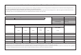
Information Concerning Inclusion of Toxic and Hazardous Substances This information sheet was prepared based on People's Republic of China ”Management Methods for Controlling Pollution Caused by Electronic Information Products Regulation”and ”SJ/T 11364—2006 Marking for Control of Pollution Caused by Electronic Information Products”.
DECLARATION OF CONFORMITY Z+200, 400, 600 and 800 SERIES We, TDK-Lambda Ltd., Located at Haharoshet St. 56 Industrial Zone P.O.B.
This page intentionally left blank
Table of Contents REGULATORY NOTICES...............................................................................................11 SAFETY INSTRUCTIONS..............................................................................................11 CHAPTER 1: GENERAL INFORMATION 1.1 User Manual Content ....................................................................................................................... 15 1.2 Introduction....................................................................
3.9.1 Load Wiring.................................................................................................................................................................. 41 3.9.2 Current Carrying Capacity.................................................................................................................................. 42 3.9.3 Wire Termination..............................................................................................................................................
5.3.4.2 Activated FOLD Alarm....................................................................................................................................... 64 5.3.5 Protection Delay....................................................................................................................................................... 64 5.3.5.1 Setting the Protection Delay......................................................................................................................... 64 5.3.
7.5 Rear Panel USB Connector............................................................................................................. 86 7.5.1 USB Getting Started................................................................................................................................................. 86 7.6 Multi Power Supply Connection to RS232 Or RS485 or USB.............................................. 86 7.7 GEN Protocol (GEN series communication language).....................................
8.5 Trigger.................................................................................................................................................. 124 8.5.1 Input Trigger............................................................................................................................................................... 124 8.5.2 Output Trigger...................................................................................................................................................
WARRANTY This TDK-Lambda product is warranted against defects in materials and workmanship for a period of five years from date of shipment. During the warranty period, TDK-Lambda will, at it’s option, either repair or replace products which prove to be defective. Limitation of Warranty The warranty shall not apply to defects resulting from improper or inadequate usage or maintenance by the buyer, buyer supplied products or interfacing.
REGULATORY NOTICES FCC Notice This device complies with Part 15 of the FCC Rules. Operation is subject to the following two conditions: (1) this device may not cause harmful interference, and (2) this device must accept any interference received, including interference that may cause undesired operation. NOTE: This equipment has been tested and found to comply with the limits for a Class A digital device, pursuant to Part 15 of the FCC rules.
CAUTION: Z+ series units are not authorized for use as critical component in nuclear control systems, life support systems or equipment for use in hazardous environments without the express written approval of the managing director of TDK-Lambda.
PARTS SUBSTITUTIONS & MODIFICATIONS Parts substitutions and modifications are by authorized TDK-Lambda service personnel only. For repairs or modifications, the instrument must be returned to TDK-Lambda service facility. AUSWECHSELN UND VERÄNDERUNG VON BAUTEILEN Das Auswechseln sowie die Veränderung von Teilen darf nur von zugelassenen TDK-Lambda Servicemitarbeitern durchgeführt werden. Für Reparaturen oder Veränderungen muss das Gerät an den TDK-Lambda Kundendienst zurückgeschickt werden.
WARNING: There is a potential shock hazard when using a power supply with output voltage greater than 42.4V. Do not turn ON power supply when output voltage above 42.4VDC without output bus-bars or output connector protection assembled. Turn OFF power supply or disconnect power supply from AC mains before making or changing any rear panel connection. WARNUNG: Beim Einsatz eines Netzteils mit einer Nenn-Ausgangsspannung von mehr als 42.4V besteht Stromschlaggefahr.
CHAPTER 1: GENERAL INFORMATION 1.1 User Manual Content This user's manual contains the operating instructions, installation instructions and specifications of the Z+ Series 200W, 400W, 600W and 800W power supply series. The instructions refer to the standard power supplies, including the built-in USB and RS232/485 serial communication. For information related to operation with the optional LAN and IEEE, refer to User Manual for power supply LAN and IEEE. 1.2 Introduction 1.2.
1.2.4 Multiple Output Power System The Z+ Series power supplies series can be configured into a programmable power system of up to 31 units using the built-in USB or RS232/RS485 communication port in the power supply and the RS485 linking cable provided with each power supply. In a LAN system, each power supply can be controlled using the optional LAN controller (factory installed). In an IEEE system, each power supply can be controlled using the optional IEEE controller (factory installed). 1.2.
CAUTION: Observe all torque guidelines within this manual. Over torque may damage unit or accessories. Such damage is not covered under manufacturers warranty. 1.3 Accessories 1.3.1 General Accessories are delivered with the power supply or separately upon ordering, The list below shows the possible accessories and ordering numbers. 1.3.2 Serial Link Cable Serial link cable, for linking power supplies by RS485 communication is provided with the power supply. Cable description: 0.
2.1 Z+200 Series Specifications MODEL 1. Rated output voltage(*1) 2. Rated output current (*2) 3. Rated output power Z ----mV mV PPM/°C ----V mS mS 18 11. Transient response time mS 12. Hold-up time (*19) --- CONSTANT CURRENT MODE 1. Max. Line regulation (*6) 2. Max. Load regulation (*11) 3. Load regulation thermal drift 4. Ripple r.m.s. 5Hz~1MHz (*12) 5. Temperature coefficient 6. Temperature stability 7. Warm-up drift Z ------mA PPM/°C ----- PROTECTIVE FUNCTIONS Z 1.
19 ANALOG PROGRAMMING AND MONITORING 1. Vout voltage programming 2. Iout voltage programming (*13) 3. Vout resistor programming 4. Iout resistor programming (*13) 5. Shut Off (SO) control 6. Output current monitor (*13) 7. Output voltage monitor 8. Power supply OK signal 9. Parallel operation (*20) 10. Series operation 11. CV/CC indicator 12. Interlock (ILC) control 13. Local/Remote mode Control 14. Local/Remote mode Indicator ----------------------------- 15.Trigger out --- 16.Trigger in --- 17.
Z+200 Series Specifications INPUT CHARACTERISTICS 1. Input voltage/freq. (*3) 2. Maximum Input current 100/200VAC (*4) (*18) 3. Power Factor (Typ) 4. Efficiency (Typ) 100/200VAC (*4) (*18) 5. Inrush current 100/200VAC (*5) ------% --- 85~265Vac continuous, 47~63Hz, single phase 2.65/1.31 2.62/1.29 >0.99 at 100Vac, >0.98 at 200Vac,100% load 76/77.5 77/79 Less than 15A/30A ENVIRONMENTAL CONDITIONS 1. Operating temperature 2. Storage temperature 3. Operating humidity 4. Storage humidity ----% % 5.
21 NOTES: *1: Minimum voltage is guaranteed to maximum 0.1% of rated output voltage. *2: Minimum current is guaranteed to maximum 0.2% of rated output current. *3: For cases where conformance to various safety standards (UL, IEC, etc…) is required, to be described as 100-240Vac (50/60Hz). *4: Ta=25°C with rated output power. *5: Not including EMI filter inrush current, less than 0.2mSec at cold start Ta=25°C *6: At 85~132Vac or 170~265VAC, constant load.
2.2 Z+400 Series Specifications MODEL 1. Rated output voltage(*1) 2. Rated output current (*2) 3. Rated output power CONSTANT VOLTAGE MODE 1. Max. Line regulation (*6) 2. Max. Load regulation (*7) 3. Ripple and noise (p-p, 20MHz) (*8) 4. Ripple r.m.s. 5Hz~1MHz 5. Temperature coefficient 6. Temperature stability 7. Warm-up drift 8. Remote sense compensation/wire 9. Up-prog. Response time, 0~Vomax.(*9) 10. Down-prog.
23 ANALOG PROGRAMMING AND MONITORING 1. Vout voltage programming 2. Iout voltage programming (*13) 3. Vout resistor programming 4. Iout resistor programming (*13) 5. Shut Off (SO) control 6. Output current monitor (*13) 7. Output voltage monitor 8. Power supply OK signal 9. Parallel operation (*21) 10. Series operation 11. CV/CC indicator 12. Interlock (ILC) control 13. Local/Remote mode Control 14. Local/Remote mode Indicator ----------------------------- 15.Trigger out --- 16.Trigger in --- 17.
Z+400 Series Specifications INPUT CHARACTERISTICS 1. Input voltage/freq. (*3) 2. Maximum Input current 100/200VAC (*4) (*18) 3. Power Factor (Typ) 4. Efficiency (Typ) 100/200VAC (*4) (*18) 5. Inrush current (*5) Z ------% --- 10-40 20-20 85~265Vac continuous, 47~63Hz, single phase 5.05/2.47 4.98/2.45 0.99 at 100/200Vac, 100% load 80/82 81/83 Less than 25A ENVIRONMENTAL CONDITIONS 1. Operating temperature 2. Storage temperature 3. Operating humidity 4. Storage humidity ----% % 5.
25 NOTES: *1: Minimum voltage is guaranteed to maximum 0.1% of rated output voltage. *2: Minimum current is guaranteed to maximum 0.2% of rated output current. *3: For cases where conformance to various safety standards (UL, IEC, etc…) is required, to be described as 100-240Vac (50/60Hz). *4: Ta=25°C with rated output power. *5: Not including EMI filter inrush current, less than 0.2mSec. *6: At 85~132Vac or 170~265VAC, constant load. *7: From No-Load to Full-Load, constant input voltage.
2.3 Z+600 Series Specifications MODEL 1. Rated output voltage(*1) 2. Rated output current (*2) 3. Rated output power CONSTANT VOLTAGE MODE 1. Max. Line regulation (*6) 2. Max. Load regulation (*7) 3. Ripple and noise (p-p, 20MHz) (*8) 4. Ripple r.m.s. 5Hz~1MHz 5. Temperature coefficient 6. Temperature stability 7. Warm-up drift 8. Remote sense compensation/wire 9. Up-prog. Response time, 0~Vomax.(*9) 10. Down-prog.
27 ANALOG PROGRAMMING AND MONITORING 1. Vout voltage programming 2. Iout voltage programming (*13) 3. Vout resistor programming 4. Iout resistor programming (*13) 5. Shut Off (SO) control 6. Output current monitor (*13) 7. Output voltage monitor 8. Power supply OK signal 9. Parallel operation (*20) 10. Series operation 11. CV/CC indicator 12. Interlock (ILC) control 13. Local/Remote mode Control 14. Local/Remote mode Indicator ----------------------------- 15.Trigger out --- 16.Trigger in --- 17.
Z+600 Series Specifications INPUT CHARACTERISTICS 1. Input voltage/freq. (*3) 2. Maximum Input current 100/200VAC (*4) 3. Power Factor (Typ) 4. Efficiency (Typ) 100/200VAC (*4) 5. Inrush current (*5) ------% --- ENVIRONMENTAL CONDITIONS 1. Operating temperature 2. Storage temperature 3. Operating humidity 4. Storage humidity ----% % 5. Altitude --- Z 10-60 20-30 85~265Vac continuous, 47~63Hz, single phase 7.48/3.69 7.22/3.56 0.99 at 100, 0.
NOTES: *1: Minimum voltage is guaranteed to maximum 0.1% of rated output voltage. *2: Minimum current is guaranteed to maximum 0.2% of rated output current. *3: For cases where conformance to various safety standards (UL, IEC, etc…) is required, to be described as 100-240Vac (50/60Hz). *4: Ta=25C with rated output power. *5: Not including EMI filter inrush current, less than 0.2mSec. *6: At 85~132Vac or 170~265VAC, constant load . *7: From No-Load to Full-Load, constant input voltage.
2.4 Z+800 Series Specifications 30 MODEL 1. Rated output voltage(*1) Vin ≥ 100Vac, Ta ≤ 50°C 2. Rated output 85Vac ≤ Vin < 100Vac, Ta ≤ 40°C current (*2)(*21) 85Vac ≤ Vin < 100Vac, 40°C < Ta ≤ 50°C Vin ≥ 100Vac, Ta ≤ 50°C 3. Rated output 85Vac ≤ Vin < 100Vac, Ta ≤ 40°C power 85Vac ≤ Vin < 100Vac, 40°C < Ta ≤ 50°C Z V A A A W W W CONSTANT VOLTAGE MODE 1. Max. Line regulation (*6) 2. Max. Load regulation (*7) 3. Ripple and noise (p-p, 20MHz) (*8) 4. Ripple r.m.s. 5Hz~1MHz 5. Temperature coefficient 6.
31 ANALOG PROGRAMMING AND MONITORING 1. Vout voltage programming 2. Iout voltage programming (*13) 3. Vout resistor programming 4. Iout resistor programming (*13) 5. Shut Off (SO) control 6. Output current monitor (*13) 7. Output voltage monitor 8. Power supply OK signal 9. Parallel operation (*20) 10. Series operation 11. CV/CC indicator 12. Interlock (ILC) control 13. Local/Remote mode Control 14. Local/Remote mode Indicator ----------------------------- 15.Trigger out --- 16.Trigger in --- 17.
Z+800 Series Specifications INPUT CHARACTERISTICS 1. Input voltage/freq. (*3) 2. Maximum Input current 100/200VAC (*4) 3. Power Factor (Typ) 4. Efficiency (Typ) 100/200VAC (*4) 5. Inrush current (*5) Z ------% --- 10-72 20-40 85~265Vac continuous, 47~63Hz, single phase 9.00/4.45 9.65/4.75 0.99 at 100Vac, 100% load / 0.98 at 200Vac, 100% load 81/83 84/86 Less than 30A ENVIRONMENTAL CONDITIONS 1. Operating temperature 2. Storage temperature 3. Operating humidity 4.
*5: Not including EMI filter inrush current, less than 0.2mSec. *6: At 85~132Vac or 170~265VAC, constant load. *7: From No-Load to Full-Load, constant input voltage. Measured at the sensing point in Remote Sense. *8: Measured with JEITA RC-9131A (1:1) probe. *9: From 10% to 90% or 90% to 10% of Rated Output Voltage, with rated resistive load. *10: From 90% to 10% of Rated Output Voltage. *11: For load voltage change, equal to the unit voltage rating, constant input voltage.
35
36
CHAPTER 3: INSTALLATION 3.1 General This chapter contains instructions for initial inspection, preparation for use and repackaging for shipment. Connection to PC, setting the communication port and linking Z+ power supplies are described in Chapter 7. NOTE: Z+ power supplies generate magnetic fields which might affect the operation of other instruments. If your equipment is susceptible to magnetic fields, do not position it adjacent to the power supply. 3.
3.5 Location, Mounting and Cooling This power supply is fan cooled. The air intake is at the front panel and the exhaust is at the rear panel. Upon installation allow cooling air to reach the front panel ventilation inlets. Allow minimum 10cm (4”) of unrestricted air space at the front and the rear of the unit. The power supply should be used in an area that the ambient temperature does not exceed +50°C.
3.7.2 AC Input Cord Refer to section 1.3.4 for details of the AC input cords recommended. WARNING: The AC input cord plug is the disconnect device of the power supply. The plug must be readily identifiable and accessible to the user. The AC input cord must be no longer than 3m. WARNUNG: Das Netzstromkabel dient zur Trennung des Netzgerätes vom Netzstrom. Der Stecker muss für den Benutzer leicht erkennbar und jederzeit zugänglich sein. Das Netzstromkabel darf nicht länger sein als drei Meter. 3.
3.8.3 Constant Voltage Check 1. Turn on the output by pressing OUTPUT button so the OUTPUT LED illuminates. 2. Observe the power supply Voltage display and rotate the Voltage encoder. Ensure that the output voltage varies while the Voltage encoder is rotated. The minimum control range is from zero to the maximum rated output for the power supply model. Compare the DVM reading with the front panel Voltage display to verify the accuracy of the Voltage display. Ensure that the front panel CV LED illuminates.
3.8.7 Foldback Check WARNING: There is a potential shock hazard when checking a power supply with output voltage greater than 42.4V. Observe proper safety procedures during the checking. WARNUNG: Beim Einsatz eines Netzteils mit einer Nenn-Ausgangsspannung von mehr als 42.4V besteht Stromschlaggefahr. Beachten Sie bei der Überprügung die entsprechenden Sicherheitsvorkehrungen. Refer to Section 5.3.4 for explanation of the FOLD function prior to performing the procedure below. 1. 2. 3. 4.
3.9.2 Current Carrying Capacity Two factors must be considered when selecting the wire size: 1. Wires should be at least heavy enough not to overheat while carrying the power supply load current at the rated load, or the current that would flow in the event the load wires were shorted, whichever is greater. 2. Wire size should be selected to enable voltage drop per lead to be less than 1.0V at the rated current.
3.9.3 Wire Termination The wires should be properly terminated with terminals securely attached. DO NOT use non terminated wires for load connection at the power supply. CAUTION: When local sensing, a short from +LS or +S to -V or -S or -LS, will cause damage to the power supply. Reversing the sense wires might cause damage to the power supply in local and remote sensing. (Do not connect -S to +V or +S to -V.) 3.9.
CAUTION: Ensure that the load wiring mounting hardware does not short the output terminals. Heavy connecting cables must have some form of strain relief to prevent loosening the connections or bending the bus-bars. 10V to 100V Models Refer to Fig.3-4 for connection of the load wires to the power supply bus-bars and to Fig.3-5 for mounting the bus-bars shield to the chassis. Fig. 3-4: Load wires connection, 10V to 100V models.
WARNUNG: Beim Einsatz eines Netzteils mit einer Nenn-Ausgangsspannung von mehr als 42.4V besteht Stromschlaggefahr. Schalten Sie die Stromversorgung mit einer Ausgangsspannung oberhalb 42.4VDC nicht auf EIN, ohne die vorhige Montierung eines Schutzes für die Ausgangssammelschiene bzw. Ausgangsbuchse. Stellen Sie sicher, dass der Schutz der Ausgangssammelschiene oder des Ausgangs aufgesetzt und angemessen montiert ist und dass der Schutz der Sammelschiene, mittels zweier SEMS-Schrauben, wie in Abb. 3.
3.9.9 Connecting Multiple Loads, Radial Distribution Method Fig.3-8 shows multiple loads connected to one supply. Each load should be connected to the power supply’s output terminals using separate pairs of wires. It is recommended that each pair of wires will be as short as possible and twisted or shielded to minimize noise pick-up and radiation. The sense wires should be connected to the power supply output terminals or to the load with the most critical load regulation requirement.
3.9.11 Grounding Outputs Either the positive or negative output terminals can be grounded. To avoid noise problems caused by common-mode current flowing from the load to ground, it is recommended to ground the output terminal as close as possible to the power supply chassis ground. Always use two wires to connect the load to the power supply regardless of how the system is grounded. WARNING: Models up to 100VDC Rated Output shall not float outputs more than +/-100VDC above/below chassis ground.
3.10.2 Local Sensing The power supply is shipped with the rear panel J2 sense connector wired for local sensing of the output voltage. Refer to Table 3-4 for J2 terminals assignment. With local sensing, the output voltage regulation is made at the output terminals. This method does not compensate for voltage drop on the load wires, therefore it is recommended only for low load current applications or where the load regulation is less critical. Fig.
CAUTION: When using shielded sense wires, ground the shield in one place only. The location can be the power supply chassis or one of the output terminals. Use remote sense where the load regulation at the load end is critical. In remote sense, the power supply will compensate for voltage drop on the load wires. Refer to the specifications for the maximum voltage drop on load wires. The voltage drop is subtracted from the total voltage available at the output.
CHAPTER 4: FRONT/REAR PANEL CONTROLS AND CONNECTORS 4.1 Introduction The Z+ Power Supply series has a full set of controls, indicators and connectors that allow the user to set up and operate the unit. Before starting to operate the unit, please read the following sections for an explanation of the functions, controls and connector terminals. - Section 4.2: Front Panel Display and Controls. - Section 4.3: Rear Panel Controls and Connectors. 4.
No. Control/Indicator Description 1 AC Power Switch AC ON/OFF control 2 Current display 4 digit 7-segment LED display. Normally displays the output current. In preview mode, the display indicates the program setting of output current. 3 Voltage Display 4 digit 7-segment LED display. Normally displays the output voltage. In preview mode, the display indicates the program setting of output voltage.
4.3 Rear Panel Connectors Refer to Fig.4-2 and Table 4-2 for description of the Rear Panel connectors. Fig. 4-2: Rear panel connections No. Connection Description Section 1 AC Input Connector IEC320-16 TYPE CONNECTOR 2 DC output bus-bar Bus-bars for 10V to 100V models. Use M6 or 1/4” screws. 3.9 3 Analog Control and signals. J1 Connector for remote analog interface. Analog control and monitoring. Referenced internally to output potential -S. 4.3.
WARNING: Terminals 7, 9 and 12 of J1 are connected internally to the negative sense(-S) potential of the power supply. Do not attempt to bias any of these terminals relative to the negative sense. Use the Isolated Programming interface option to allow control from a programming source at a different potential relative to the power supply negative. CAUTION: To prevent ground loops and to maintain the isolation of the power supply when programming from J1, use an ungrounded programming source.
4.3.1 J1 Connector Terminal and Function Control and monitoring signals are referenced to the negative sense potential (-S). Connector Technical Information: •• Connector type: IPL1-106-01-S-D-RA-K, SAMTEC •• Receptacle type: IPD1-06-D-K, SAMTEC •• Contact pins: CC79R-2024-01-L, SAMTEC •• Hand tool: CAT-HT-179-2024-11, SAMTEC •• Wire: AWG 20-24 Fig.
4.3.2 J3 Connector Terminal and Function Control and monitoring signals are isolated from the power supply output. Connector Technical Information •• Connector type: IPL1-104-01-S-D-RA-K, SAMTEC •• Receptacle type: IPD1-04-D-K, SAMTEC •• Contact pins: CC79R-2024-01-L, SAMTEC •• Hand tool: CAT-HT-179-2024-11, SAMTEC •• Wire: AWG 20-24 Fig.4-4: J3 connector terminals and functions Pin Signal name Function Section 1 Programmed Signal 1 General Purpose Open collector Port 1 5.7.
4.4 Front Panel Display Messages Table 4-5 shows the various messages that will be shown on the display in different operating modes. Display Text Text Description Display Text Text Description Abor ABORT ON ON AC AC ONCE ONCE Adr ADDRESS OTP OTP AUTO AUTO (RESTART) OuP OVP bAUD BAUD RATE PRLL PARALLEL BUS BUS Pin1 PIN 1 Cont CONTINUE Pin2 PIN 2 COUN COUNTER POS POSITIVE CvRR CURRENT PROG PROGRAM CC CC PR.
4.5 Navigating the Main Menu 4.5.1 Introduction The Main Menu consists of three levels: Subsystem, Function and Parameter. To enter the Menu press the Menu button. The Menu LED illuminates and the display shows the Subsystem Menu. Navigate by rotating the Voltage encoder to scroll through the Subsystem list (first level). Repeat these actions to navigate the Functions list (second level). In the third level, the Voltage display shows the function and the Current display shows the parameter.
4.5.2 Exiting the Main Menu There are three ways to exit from Main Menu: 1. Press MENU button twice. MENU LED turns OFF. Display shows present status of power supply. 2. Press and hold MENU button 3sec. MENU LED turns OFF. Display shows present status of power supply. 3. No action for 15 sec. MENU LED turns OFF. Display shows present status of power supply. 4.6 Navigating Communication Menu 4.6.1 Introduction The Communication Menu consists of two /three levels: Function level and Parameter level.
4.6.2 Exiting the Communication Menu There are three ways to exit from REM menu: 1. Press REM button. 2. No action for 15sec. REM LED turns OFF. Display shows present status of power supply. 4.7 Navigating the Protection Menu 4.7.1 Introduction The Protection Menu consists of two levels: Function and Parameter. To navigate the Protection Menu press PROT button. The PROT GREEN LED illuminates. The function menu item appears on the display.
CHAPTER 5: LOCAL OPERATION 5.1 Introduction This Chapter describes the operating modes that do not require programming and monitoring the power supply via its serial communication ports. USB or RS232/RS485 or by remote analog signals. Ensure that the REM LED on the front panel is Off, (indicating Local mode). If the REM LED is On, press the front panel REM button to change the operating mode to local. - For information regarding remote analog programming refer to Chapter 6.
5.2.3 Automatic Crossover When the power supply operates in Constant Voltage mode, while the load current is increased to greater than the current limit setting, the power supply will automatically switch to Constant Current mode. If the load is decreased to less than the current limit setting, the power supply will automatically switch back to Constant Voltage mode. 5.2.4 Output On/Off Control The Output On/Off enables or disables the power supply output.
5.3 Alarms and Protective Functions 5.3.1 Introduction There are several conditions that cause alarm (RED LED blinks). All alarms affect the output. When an alarm occurs, the respective fault will appear on the display and the alarm LED illuminates. It is possible that more than one fault (alarm) may be triggered but only the first will be shown on the display. If the second fault is still active when the first fault is removed, then the second fault will be displayed.
5.3.2.2 Resetting the OVP Circuit To reset the OVP circuit after activation: 1. Reduce the power supply Output Voltage setting below the OVP set level. 2. Ensure that the load and the sense wiring is connected properly. 3. Four methods to reset the OVP circuit. • Press OUTPUT button. • AC recycle. • On/Off recycle by analog control (Interlock). • Send communication command to enable output. 5.3.
5.3.4.1 Setting the Foldback Protection The Foldback can be set when the power supply output is Enabled (On) or Disabled (Off ). 1. Press PROT button. PROT (GREEN) LED illuminates. The ”OUP” message appears on the Voltage display. 2. Rotate Voltage encoder until ”” message appears on Voltage display. 3. Press Voltage encoder. ”” message appears on Voltage Display, and on Current display shows ”” or ”” or ”” setting mode. 4.
5.4 Series Operation Power supplies of the same model can be connected in series to obtain increased output voltage. Split connection of the power supplies gives positive and negative output voltage. 5.4.1 Series Connection for Increased Output Voltage Two units are connected so that their outputs are summed. Set the current limit of each power supply to the maximum that the load can handle without damage.
5.4.3 Remote Programming in Series Operation Programming by external voltage: The analog programming circuits of this power supply are referenced to the negative Sense potential. Therefore, the circuits used to control each series connected unit must be separated and floated from each other. Refer to section 6.4 Using the SO function and PS_OK signal : The Shut Off and PS_OK circuits are referenced to the isolated interface common, IFC_COM (J3-7).
5.5 Parallel Operation 5.5.1 Introduction Up to six units of the same Voltage and Current rating can be connected in parallel to provide up to six times the output current capability. One of the units operates as a master and the remaining units are slaves. The slave units are analog programmed by the master unit. In remote digital operation, only the master unit can be programmed by the computer while the slave units may be connected to the computer for voltage, current and status readback only.
5.5.2.2 Slave Unit Set Up When Slave mode is selected the power supply enters Current programming mode via external Voltage. Voltage and Current programming setting values are set to 105% of range. During operation the slave units operate as a controlled current source following the master output current. It is recommended that the power system is designed so that each unit supplies up to 95% of its current rating. This helps reduce imbalance which may occur by cabling and connections voltage drop. 1. 2. 3.
Fig.5-5: Parallel operation with remote sensing CAUTION: Make sure that the connection between - Vo terminals is reliable to avoid disconnection during operation. Disconnection may cause damage to the power supply. NOTE: With local sensing it is important to minimize the wire length and resistance. Also the positive and negative wire resistance should be as close as possible to each other to achieve current balance between power supplies.
5.5.3 Advanced Parallel Operation In Advanced Parallel operation the master unit displays the total current of all units connected in Parallel. The slave units display ”ON SLUE”. The master and slave units operate in a Daisy-Chain connection configuration. For further details about Daisy-chain connection refer to section 5.6. In the Advanced Parallel mode, the total current is programmed and reported by the master unit. The Current display accuracy is 2%+/- 1 count.
5.6 Daisy-Chain Connection It is possible to configure a multiple power supply system to shut down all units when a fault condition occurs in one of the units. When the fault is removed, the system recovers according to a preset state: Safe start mode or Automatic restart. Set signal ”SO” to positive logic via Front panel (refer to section 5.7.1) . If a fault occurs in one of the units it’s ”PS_OK” signal will be set to low level and the display will indicate the fault.
5.7.1 External Shut Off Function SO signal serves as Output Shut Off . It is an optically isolated signal from the power supply output. Connection to the signal is made via pin J3-5 (Shut Off ) and pin J3-7 (IFC_COM). The SO pin accepts a 2.5V to 15V signal or Open-Short contact to disable or enable the power supply output. The SO function will be activated only when a transition from On to Off is detected after applying AC power to the unit.
Front Panel ILC Setting ILC Input Power Supply Output Display Alarm LED OFF - Default Open or Short On Voltage/Current Off Open Off EnA Blinking Short On Voltage/Current Off ON Table 5-5: Interlock functions and settings CAUTION: To prevent possible damage to the unit, do not connect any of the Enable /Disable inputs to the positive or negative output potential.
5.7.4 Power Supply OK Signal PS_OK signal indicates fault condition in the power supply. It is a TTL signal output at J3-2, referenced to IFC_COM at J3-7 (Isolated Interface Common). When a fault condition occurs, PS_OK level is low, with maximum sink current of 1mA. When no fault condition occurs, PS_OK level is high with maximum source current of 2mA. All conditions when output status is disabled sets PS_OK to low level. The PS_OK signal at high level can be delayed via Front panel setting or software.
5.9 Parameter Setting Memory Power Supply has four memory configuration modes: Subsystem Level Memory Display Function Level Display Parameter Level Display Description SAVE 1…4 Save setting in non violate memory RECALL 1…4 Recall setting in non violate memory RST YES Reset setting FRST YES Set factory default setting Table 5-6: Parameter Setting Memory 5.9.1 Default Setting For factory default parameters refer to Table 5-7. 1.
5.9.4 Save <1..4> This command saves the present state of the power supply to a specified location in memory (refer to Table 5-7). Up to 4 states can be stored. Storage locations 1 through 4 are in nonvolatile memory. Save Front panel setting: 1. Press MENU button. MENU (green) LED illuminates. ”” message appears on the Voltage display. 2. Rotate Voltage encoder until ”” message appears on Voltage display. 3. Press Voltage encoder. ”” message appears on Voltage display. 4. Press Voltage encoder.
Parameter Output Status Factory Default Resetting Last setting Save & Recall OFF OFF + + Voltage Set-point 0V 0V + + Current Set-point MAX 0A + + Fold Back mode OFF OFF + + Over Voltage Protection OVP MAX MAX + + Under Voltage Level/ Protection mode OFF (UVL) OFF (UVL) + + Under Voltage Level/ Protection level 0V 0V + + SAFE SAFE + + Control pin 1 1 1 + + Control pin 2 1 1 + + EXT EXT + - Auto Start Mode Input Trigger Source 0mS 0mS + + Voltage
CHAPTER 6: REMOTE ANALOG PROGRAMMING 6.1 Introduction The Rear Panel connector J1 allows the user to program the power supply output voltage and current limit with an analog device. J1 also provides monitoring signals for output voltage and output current. The programming range and monitoring signals range can be selected between 0-5V or 0-10V using the Front Panel Menu Subsystem Level.
6.4 Remote Voltage Programming of Output Voltage and Current Remote Programming settings are as follows: 1. 2. 3. 4. 5. 6. 7. 8. 9. 10. 11. 12. For Voltage Analog Programming wiring refer to Fig.6-1. Short pins J1-1 to J1-7. Press MENU button. MENU (GREEN) LED illuminates. ”Set” message appears on Voltage display. Press Voltage encoder. ”uOLt” message appears on Voltage Display and ”CvRR” appears on the Current display.
6.5 Remote Resistor Programming of Output Voltage and Output Current For resistive programming, internal current sources, for output voltage and/or output current control, supply 1mA current through external programming resistors connected between J1-6 and J1-12 and between J1-5 and J1-1, J1-7 & J1-11. The voltage across the programming resistors is used as a programming voltage for the power supply.
1. 2. 3. 4. 5. 6. NOTES: In Remote analog mode: the output voltage cannot be set by the Voltage encoder. The output voltage limit is set to 5% over the model-rated maximum value. The output Current limit is set by the Current encoder to 5% over the model-rated maximum value. The power supply will operate within the extended range, however it is not recommended to operate the power supply over its voltage and current rating and performance is not guaranteed.
CHAPTER 7: Serial RS232/RS485 and USB Interface 7.1 Introduction This chapter describes the set-up, operation, commands and communication protocol of Z+ power supplies via serial communication interfaces: RS232, RS485 or USB. 7.2 Configuration Function Level Interface Display N Parameter Level Display 232 485 USB LAN IEEE Address 1….31 1 Baud Rate 1200..
7.2.4 Baud Rate Setting Seven optional rates are possible: 1200, 2400, 4800, 9600, 19200, 38400, 57600. 1. Press REM button. The REM LED illuminates. ”N” message appears on the Voltage display. 2. Rotate Voltage encoder until Voltage display shows ” ”. 3. Press Voltage encoder. Voltage display shows ” ” and Current display shows baud rate. 3. Rotate the Current encoder to select required baud rate. 4. Press Current encoder to enter selected parameter to memory. 5.
7.3 Rear Panel RS232/485 Connector The RS232/485 interface is accessible through the Rear panel RS232/485 IN and RS485 OUT connectors. The connectors are 8 contact RJ-45. The IN and OUT connectors are used to connect power supplies in a RS232 or RS485 chain to a controller. Refer to Fig.7-1 for IN/OUT connectors. Shield (Connector enclosure) OUT NC NC TXDRXDRXD+ TXD+ NC SG 8 7 6 5 4 3 2 1 1 2 3 4 5 6 7 8 SG NC RXD+ TXD+ TXDRXDTX RX IN Fig.
7.4 Connectig Power Supply To RS232 Or RS485 BUS Connect rear panel IN connector to the controller RS232 or RS485 port using a suitable shielded cable. Refer to Figures 7-2, 7-3 and 7-4 for available RS232 and RS485 cables. Socket 08-25 CONNECTOR PIN NO. NAME 1 SHIELD 2 TX 3 RX 7 SG 8 PIN CONNECTOR PIN NO. NAME HOUSING SHIELD 8 RX 7 TX 1 SG REMARKS TWISTED PAIR Fig.7-2: RS232 cable with DB25 connector (P/N: Z/232-25) Socket D08-9 CONNECTOR PIN NO.
7.5 Rear Panel USB Connector A standard USB Series B device connector is located on Rear panel for USB control. Refer to Fig.7-5 and Table 7-2. 1 2 3 4 Fig.7-5: USB Connector Pin Designator Description 1 VBUS +5 VDC 2 D- Data - 3 D+ Data + 4 GND Interface com Table 7-2: USB connector pin out 7.5.1 USB Getting Started USB Cable connect to USB port The following steps will help you quickly get started connecting your USB-enabled instrument to the Universal Serial Bus (USB): 1.
NOTES: RS485 RS485 RS232/485 RS485 It is recommended when using ten or more power supplies in Daisy-chain system to connect 120Ω resistive termination at the last unit’s RS-485 out connector RS485 120 OHM 120Ω, 0.5W between TXD+ and TXD-. #3 #1 #31 120Ω, 0.5W between RXD+ and#2RXD-. L=0.5m typ. 8 1 8 1 8 PIN CONNECTOR (IN) PIN NO. NAME HOUSING SHIELD 1 SG 6 TXD3 TXD+ 5 RXD4 RXD+ 8 PIN CONNECTOR (OUT) PIN NO. NAME HOUSING SHIELD 1 SG 6 RXD3 RXD+ 5 TXD4 TXD+ Fig.
Error Code Description E01 Returned when program voltage (PV) is programmed above acceptable range. Example: PV above 95% of OVP setting. E02 Returned when programming output voltage below UVL setting. E04 Returned when OVP is programmed below acceptable range. Example: OVP value is less than 105% of voltage setting. E06 Returned when UVL value is programmed above the programmed output voltage. E07 Returned when programming the Output to ON during a latched fault shut down.
7.8.4 Initialization Commands Command Description ADR n ADR is followed by address which can be 1 to 31 and is used to access the power supply . CLS Clear status. Sets FEVE and SEVE registers to zero. RST Reset command. Brings the power supply to a safe and known state: Output voltage: zero, Remote: non-latched remote, Output current: zero, Auto-start: Off, Output: Off, OVP: maximum, FOLD: Off, UVL: zero The conditional registers (FLT and STAT) are updated, the other registers are not changed.
Command OUT n OUT? FLD n FLD? FBD nn FBD? FBDRST OVP n OVP? OVM UV? UVL n UVL? UVP n UVP? AST n AST? SAV n RCL n MODE? PMS n PMS? 1. 2. 3. 4. Description Turns the output to ON or OFF. Recover from Safe-Start, OVP or FLD fault. OUT 1 (or OUT ON)-Turn On. Returns the output On/Off status string. ON- output on. OFF- output off. Sets the Foldback protection to ON or OFF. FLD 1 (or FOLD ON) - Arms the Foldback protection. FLD 0 (or FOLD OFF)- Cancels the Foldback protection.
7.8.6 Global Output Commands General Global commands can be received by all power supplies connected to the BUS, without individual address commands. All power supplies will execute the command immediately. There is no acknowledgment back to the PC when using global commands. A delay must be set of 20msec after each global command. Error messages are not reported back to the issuing PC. GRST Reset.
Model Minimum (A) Maximum (A) Model Minimum (A) Maximum (A) 10-20 00.00 20.00 10-40 00.00 40.00 20-10 00.00 10.00 20-20 00.00 20.00 36-6 0.000 6.000 36-12 00.00 12.00 60-3.5 0.000 3.500 60-7 0.000 7.000 100-2 0.000 2.000 100-4 0.000 4.000 Table 7-6: Z200 models Current programming range Model Minimum (A) Maximum (A) 10-72 00.00 72.00 20-40 00.00 40.00 36-24 00.00 24.00 60-14 00.00 14.00 100-8 00.00 8.
7.8.7 Auxiliary Commands SOP Sets SO polarity ”SO 1/ON” –Positive (default), ”SO 0/OFF”-Negative SOP? Returns the SO polarity RIE Remote Interlock (Inhibit) enable. ”RIE 1/ON”-Enable, ”RIE 0/OFF”-Disable” RIE? Returns Interlock enable status. ”ON” –interlock enable, ”OFF”-interlock disable. FRST Factory reset command. This command cover *RST command and additional settings. Sets factory default. This command breaks communication. Refer to Table 5-7. MP? Reads the actual output power.
7.9 Serial Communication Test Set-Up Basic set-up to test serial communication operation. 1. Equipment: PC with Windows Hyper Terminal, private edition, software installed, Z+ power supply, RS232 cable. 2. PC set-up: 2.1 Open Hyper Terminal.......................New Connection. 2.2 Enter a name 2.3 Connect to.......................................Direct to Com1 or Com 2 2.4 Configure port properties: Bits per second .......9600 Data bits ..................8 Parity .......................None Stop bits...
7.10.4 Checksum The user may optionally add a checksum to the end of the command. The checksum is ”$” followed by two hex characters. If a command or a query has checksum, the response will also have one. There is no CR between the command string and the ”$” sign. 7.10.5 SCPI Requirements The power supply conforms to the following SCPI requirements: 1. SCPI common commands. 2. SCPI Command Tree. 3 Subsystem commands. 4. The ROOT level. 5. The power supply is powered On 6.
7.10.8 Data Formats Data Formats Description Digits with an implied decimal point assumed at the right of the least-significant digit. Examples: 256 Digits with an explicit decimal point. Example: .0253 Digits with an explicit decimal point and an exponent. Example: 2.73E+2 Extended format that includes , and . Examples: 273 273.1 2.73E2 Expanded decimal format that includes and MIN MAX. Examples: 273,273.1, 2.73E2, MAX.
*ESE Standard Event Status Enable command. Modifies the contents of the Event Status Enable Register.
*OPC Operation Complete command. Sets the Operation Complete bit in the Standard Event Status Register if all commands and queries are completed. Meaning and Type Operation Complete Command Syntax *OPC Parameters None Device Status *OPC? Operation Complete query. Returns ASCII ‘1’ as soon as all commands and queries are completed.
*RCL n Restores the power supply to a state previously stored in memory by *SAV command. Refer to Table 5-7. Command Syntax *RCL Parameters 1 to 4 Exmple *RCL 3 *RST This command resets the power supply to a defined state as shown in Table 5-7. *RST also forces an ABORt command. Command Syntax *RST Parameters None *SAV n The SAV command saves all applied configuration setting. Refer to Table 5-7.
*STB? Status Byte query. Returns the contents of the Status Byte Register.
7.12 SCPI Subsystem Commands Subsystem commands are specific to power supply functions. They can be a single command or a group of commands. Groups are comprised of commands that extend one or more levels below the root. Commands followed by a question mark (?) take only the query form. Except as noted in the syntax descriptions, all other commands take both the command and query form. 7.12.1 Output Subsystem OUTPut This command enables or disables the power supply output.
OUTPut:PROTection:FOLDback Foldback mode is used to disable the output when a transition is made between the operation modes. The power supply will turn off the output after a specified delay if the power supply makes transition into CV mode or into CC mode. This feature is particularly useful for protecting current or voltage sensitive loads. SCPI Command Syntax OUTPut:PROT:FOLDback[:MODE] GEN Command Syntax FLD Parameters OFF|0, CC|1, CV|2 .
OUTPut:TTLTrg:MODE Sets the operation of the Trigger Out signal to either OFF, Function Strobe or Trigger mode. Programming Mode NONE, FIX: •• In TRIG mode, trigger is generated when output status changes. •• In Function Strobe mode, an output pulse is generated automatically any time an output parameter such as output, voltage or current is programmed. Programming modes LIST or WAVE: •• In TRIG mode, trigger is generated when LIST or WAVE is completed.
7.12.2 Instrument Subsystem The subsystem programs one or more power supplies. from 1 to 31. INSTrument:COUPle SCPI Command Syntax INSTrument:COUPle GEN Command Syntax None Parameters ALL|NONE INSTrument:NSELect SCPI Command Syntax INSTrument:NSELect GEN Command Syntax ADR n (single address) Examples INSTrument:NSELect 6 Query Syntax INSTrument:NSELect? 7.12.3 Voltage Subsystem VOLTage Sets the output voltage value in Volts.
NOTE: VOLT:MODE LIST and WAVE is an implied ABORT command. WAVE mode cannot be programmed simultaneously for both Voltage and Current. Only the last sent command can be accepted as WAVE. Previous mode reverts to NONE. VOLTage:PROTection:LEVel Sets the OVP level. The OVP setting range is given in Table 7-9. The number of characters after OVP is up to 12. The minimum setting level is approx. 105% of the set output voltage, or the value in Table 7-9, whichever is higher.
VOLTage:PROTection:LOW Sets the under voltage protection (UVP) level of the power supply. SCPI Command Syntax [SOURce]:VOLTage:PROTection:LOW GEN Command Syntax UVL < NRf+> , UVP < NRf+> Default Suffix V *RST Value 0 Examples VOLT:PROT:LOW 2.5 Query Syntax [SOURce]:VOLTage:PROTection:LOW [:LEVel]? VOLT:PROT:LOW? MIN; VOLT:PROT:LOW? MAX Returned Parameters VOLT:PROT:LOW? returns presently programmed UVP level.
CURRent:MODE This command selects FIX, LIST, WAVE subsystems control over the power supply output current. SCPI Command Syntax [SOURce]:CURRent:MODE GEN Command Syntax None Parameters NONE | FIXed | LIST | WAVE *RST Value NONE Examples CURR:MODE LIST CURR:MODE FIX Query Syntax [SOURce]:CURRent:MODE? Returned Parameters NONE | FIX | LIST | WAVE CURRent:TRIGger Programs the pending triggered current level of the power supply.
MEASure:VOLTage? Reads the measured output voltage. Returns a 5 digit string. SCPI Command Syntax MEASure:VOLTage? GEN Command Syntax MV? Parameters None Default Suffix V Returned Parameters MEASure:POWer? Reads the measured output power. Returns a 5 digit string. SCPI Command Syntax MEASure:POWer? GEN Command Syntax MP? Parameters None Default Suffix W Returned Parameters 7.12.6 DISPlay Subsystem DISPlay:STATe Turns front panel voltage and Current display toggle On or Off.
7.12.7 INITiate Subsystem INITiate Enables the trigger subsystem. If a trigger circuit is not enabled, all trigger commands are ignored. SCPI Command Syntax INITiate[:IMMediate] GEN Command Syntax None Parameters None Examples INIT:IMM Query Syntax None INITiate:CONTinuous •• INIT:CONT 0 - Enables the trigger subsystem only for a single trigger action. The subsystem must be enabled prior to each subsequent trigger action.
LIST:CURRent Specifies the output current points in a list. The current points are given in the command parameters, which are separated by commas. SCPI Command Syntax [SOURce]:LIST:CURRent {,} Default Suffix A Examples LIST:CURR 2.5,3.0,3.5 LIST:CURR MAX,2.5,MIN Query Syntax LIST:CURRent? Returned Parameters 2.5,3.0,3.5 up to 12 parameters LIST:LOAD Loads from memory LIST type. Type voltage/current values, dwell values, STEP parameter and counter specified in stored numbers <1..
LIST:VOLTage Specifies the output voltage points in a list. The voltage points are given in the command parameters, which are separated by commas. SCPI Command Syntax [SOURce]:LIST:VOLTage {,} Default Suffix V Examples LIST:VOLT 2.0,2.5,3.0 LIST:VOLT MAX,2.5,MIN Query Syntax LIST:VOLT? Returned Parameters 2.0,2.5,3.0 up to 12 parameters LIST:STORe Saves data under specified numbers <1..4> of the last LIST typed (voltage or/and current, dwell time, STEP parameter and counter).
STATus:OPERation:ENABle Sets the value of the Enable register. This register is a mask for enabling specific bits from the Condition register to the Event register.
7.12.10 SYSTem Subsystem SYSTem:ERRor:ENABle Enables Error messages. SCPI Command Syntax SYSTem:ERRor:ENABle GEN Command Syntax None Parameters None Returned Parameters None SYSTem:ERRor? Returns the next error number and corresponding error message in the power supply error queue. Works as FIFO. When no error exists 0, ”No error” is returned.
SYSTem:DATE? SCPI Command Syntax SYSTem:DATE? GEN Command Syntax DATE? Query Syntax SYSTem:DATE? Returned Parameters yyyy/mm/dd SYSTem:PON:TIME? Time measured from first power On. SCPI Command Syntax SYSTem:PON:TIME? Parameters Minute Example 6534 Returned Parameters 7.12.11 TRIGger Subsystem NOTE: The Trigger subsystem must be enabled from the Initiate subsystem or no triggering action will occur.
TRIGger:SOURce Selects the power supply input trigger source as follows: •• BUS (*TRG & TRIG) and Front Panel •• EXT Mainframe backplane Trigger IN PIN SCPI Command Syntax TRIGger[:STARt]:SOURce GEN Command Syntax None Parameters BUS | EXTernal *RST Value EXTernal Examples TRIG: SOUR BUS Query Syntax TRIGger[:STARt]:SOURce? Returned Parameters BUS | EXT 7.12.12 WAVE Subsystem This subsystem receives parameters to create a sloped waveform of the output voltage or current.
WAVE:STEP •• WAVE:STEP AUTO - When triggered, creates waveforms consecutively, until the wave is completed. •• WAVE:STEP ONCE - When triggered, it executes one step from the list. SCPI Command Syntax [SOURce]WAVE:STEP Example WAVE:STEP AUTO Query Syntax [SOURce]:WAVE:STEP? Returned Parameters AUTO | ONCE WAVE:STORe Stores Voltage or Current, Time, STEP parameter and counter values to specific location in the memory defined by numbers <1..4>.
Global Commands List Command Name Description SCPI Format GEN Format Result From Supply Enable all Outputs Output On to last V & I levels GLOBal:OUTPut:STATe 1|ON GOUT 1 None Disable all Outputs Turn outputs Off to zero V & I GLOBal:OUTPut:STATe 0|OFF GOUT 0 None Program all Voltages Set all power supply output voltage GLOBal:VOLTage:[AMPLitude] xxx.yy GPV xxx.yy None Program all Currents Set all power supply output current GLOBal:CURRent:[AMPLitude] xxx.yy GPC xxx.
Subsystem Commands SCPI Command Description GEN Command ABORt Aborts the triggered action [:WINDow]:STATe Display ON/OFF [:WINDow]:FLASh Display Flash Set the output current for all power supplies GPC Set the output voltage for all power supplies GPV Enables/disables the all power supplies output GOUT DISPlay GLOBal :CURRent :[AMPLitude] :VOLTage :[AMPLitude] :OUTPut:STATe *RCL {1|2|3|4} Recall setting for all power supplies GRCL *RST
:RELay {1|2} [:STATe] :MODE? Set control pins status REL{1|2}[?] Returns the operation mode CV/CC/OFF MODE? [:AMPLitude] Set the output current PC[?] Set the triggered output current [SOURce] :CURRent [:LEVel] [:IMMediate] [:AMPLitude] :TRIGger :MODE NONE|FIX|LIST|WAVE Select arbitrary trigger control mode :VOLTage [:LEVel] [:IMMediate] [:AMPLitude] Set the output voltage PV[?] Set the triggered output voltage Set over-voltage protection lev
STATus :OPERation [:EVENt]? Returns the value of the Event register SEVE? :CONDition Returns the value of the Condition register STAT? :ENABle Enables specific bits in the Event register SENA[?] [:EVENt]? Returns the value of the Event register FEVE? :CONDition Returns the value of the Condition register FLT? :ENABle Enables specific bits in the Event register FENA[?] Enable error message :QUEStionable SYSTem :ERRor:ENABle :ERRor? Read system error messages :LAN
CHAPTER 8: ADVANCED FUNCTIONS 8.1 Introduction This chapter describes the advanced functions of output programmable modes. The are three programmable modes: FIX, WAVE and LIST. The user can program the output transient state. The programmable modes are synchronized by input trigger (refer to section 8.5.1). According to the selected mode, the power supply activates the output trigger on J3-3 (refer to section 8.5.2). 8.2 FIX Mode Output value is changed via input trigger. Refer to 7.12.
8.3 LIST Mode Output change value in step determined by parameters in the LIST subsystem via input trigger. Refer to section 7.12.8 Fig.8-3: Simplified Models of LIST Mode 0.01sec Trig Initated INIT:IMM WTG (Wait Trigger) Trigger Event TDC TRIG:DEL 0.02 0.02s STS DWELL (Step Started) 0.05s 0.06s 0.03s LIST:DWELL 0.05,0.06,0.03 STC (Step Complited) OPC (Operation Complited) OUTPUT VOLTAGE LIST:VOLT 5,10,0 LIST STEP AUTO Fig.
8.4 WAVE Mode Output change value in slope determined by parameters in the WAVE subsystem via input trigger. Refer to section 7.12.12. Fig.8-5: Simplified Models of Trigger in WAVE Mode 0.01sec Trig Initated INIT:IMM WTG (Wait Trigger) Trigger Event TRD 0.02s TRIG:DEL 0.02 STS TIME (Step Started) 0.03s 0.02s 0.03s 0.03s 0.02s 0.03s WAVE:TIME 0,3,2,3 STC (Step Complited) OPC (Operation Complited) WAVE:VOLT 5,10,10,0 OUTPUT VOLTAGE WAVE:COUN 2 INIT CONT 0 WAVE MODE AUTO Fig.
8.5 Trigger Subsystem Level Trigger Setting Display G Function Level Display INIT n Continue n Trigger IN (input trigger) Trigger delay Trigger OUT Programming G Parameter Level Display Description INIT TRIG G Initialization (Refer to command INIT) ready for trigger. ENA n DIS BUS (via Software or front Panel), EXT (Analog) 0-65sec OFF Trigger G Function Strobe .
8.5.2 Output Trigger Rear panel connector J3-3 (Refer to section 4.3.2). There are three output trigger modes: Programming Mode NONE, FIX: •• OFF – No Trigger out. •• In TRIG mode, trigger is generated when output status changes. •• In Function Strobe mode, an output pulse is generated automatically any time an output parameter such as output, voltage or current is programmed. Programming modes LIST or WAVE: •• OFF – No Trigger out. •• In TRIG mode, trigger is generated when LIST or WAVE is completed.
8.6.3 Wave Execution via Front Panel 1. Load stored data MENU -> ”G” -> ”” -> 2. Set Trigger IN source ( BUS for Command or Front Panel and EXT via Rear Panel J3.2 pin) MENU -> ”G”-> ” I” -> ”” 3. Set Trigger Initialize Continue mode (If 1 then after program execution power supply will be ready for the next trigger. If 0 then send INIT command MENU -> ”G” -> ”o n” -> ”n” to get to the next trigger. 4. Set INIT command.
CHAPTER 9: STATUS, FAULT AND SRQ REGISTERS 9.1 General This section describes various status errors (faults) and SRQ register structures. The registers can be read or set via the RS232/485/USB commands. Refer to Fig.9-1 for the Status and Fault Registers Diagram. Fig.
9.2 Power Supply Status Structure Status and Fault Register shows the status register structure of the power supply. The Standard Event, Status Byte, and Service Request Enable registers and the Output Queue perform standard functions as defined in the IEEE 488.2 Standard Digital Interface for Programmable Instrumentation. The Operation Status and Questionable Status registers implement status functions specific to the power supply. 9.
9.3.2 Status Register The status register sets a bit when status changes (Refer to Table 9-2). The bit is cleared when the condition is removed.
9.6 Standard Event Status Group 9.6.1 Register Functions This group consists of an Event register and an Enable register that are programmed by COMMON commands. The Standard Event register latches events relating to interface communication status. It is a read-only register that is cleared when read. The Standard Event Enable register functions similarly to the Enable registers of the Operation and Questionable status groups. 9.6.
9.6.3 Status Byte Register This register summarizes the information from all other status groups as defined in the IEEE 488.2 Standard Digital Interface for Programmable Instrumentation standard. The register can be read either by a serial poll or by *STB?. Both methods return the same data, except for bit 6. Sending *STB? return MSS in bit 6, while polling returns RQS in bit 6. The *CLS command will clear the Status Byte.
9.6.5 Output Queue The Output Queue is a first-in, first-out (FIFO) data register that stores power supply-to-controller messages until the controller reads them. Whenever the queue holds one or more bytes, it sets the MAV bit (4) of the Status Byte register. If too many unread error messages are accumulated in the queue, a system error message is generated. The Output Queue is cleared at power On and by *CLS. 9.6.6 Error Messages System Error Messages are read back via the SYST:ERR? query.
Error Error Description Number Error Event 0 ”No Error” No Error Reported -100 ”Command Error” Unit Receives Command With Unspecified Error. -101 ”Invalid Character” A Character Was Received That Is Not: A-Z, A-Z, 0-9, ?, *, :, ;, Period, Space, CR, LF. -104 ”Data Type Error” IEEE Receives Command Parameter With Wrong Type Of Data. Example: Receives Letter Where Number Expected. -109 ”Missing Parameter” Valid Command Received But Not Enough Characters.
CHAPTER 10: ISOLATED ANALOG PROGRAMMING OPTION 10.1 Introduction Isolated Analog Programming is an internal option card for analog programming of the Z+ Power Supply series. The option is factory installed and cannot be obtained with GPIB (IEEE) Interface. Output Voltage and Current Limit can be programmed and readback through optically isolated signals which are isolated from all other ground references in the power supply. There are two types of Isolated Analog programming cards: 1.
10.3 Isolated Programming & Monitoring Connector Refer to Table 10-1 for detailed description of the Rear Panel Isolated Programming & Monitoring connector. To provide the lowest noise performance, it is recommended to use shielded-twisted pair wiring. Refer to Fig.10-1 for description of the connector. Isolated programming plug P/N: MC1.5/8-ST-3.81, Phoenix. 1 2 3 4 5 6 7 8 Shield Shield +VPROG_ISO +IPROG_ISO GND +IMON_ISO +VMON_ISO GND Fig.
10.4 Setup and Operating Instructions CAUTION: To prevent damage to the unit, do not program the output voltage and current to higher than the power supply rating. 10.4.1 Setting Up Power Supply for 0-5/0-10V Isolated Programming and Monitoring Perform the following procedure to configure the power supply: 1. Turn the power supply AC power switch to Off. 2. Short pins J1-1 to J1-7, and turn AC power switch to On. 3. Press MENU button. MENU (GREEN) LED illuminates. ”Set” message appears on Voltage display.
CHAPTER 11: MAINTENANCE 11.1 Introduction This chapter provides information about maintenance, calibration and troubleshooting. 11.2 Units Under Warranty Units requiring repair during the warranty period should be returned to a TDK Lambda authorized service facility. Refer to the address listings on the back cover of this manual. Unauthorized repairs performed by other than the authorized service facilities may void the warranty. 11.
SYMPTOM ACTION Check continuity, replace Is the AC power cord defective? if necessary. REF. Is the AC input voltage within range? Check input AC voltage. Connect to appropriate voltage source. 3.6 3.7 Output is present momentarily Does the AC source voltage sag Check input AC voltage. but shuts off quickly. The display when load is applied? Connect to appropriate voltage source. indicates ”AC”. 3.6 No output. All displays and indicators are blank.
11.1 Einleitung Dieses Kapitel liefert Informationen über Wartung, Kalibrierung und Fehlersuche. 11.2 Reparaturen während der Garantie Sollte ein Gerät innerhalb der Garantiezeit ausfallen, so dürfen Reparaturen nur durch Lambda oder autorisierte Servicestellen durchgeführt werden. Die Adressen finden Sie am Ende dieses Handbuches. Eingriffe in die Geräte durch nicht autorisierte Stellen führen zum Verlust des Garantieanspruches. 11.3 Periodische Wartung Die Geräte sind wartungsfrei.
Symptom Prüfung Tätigkeit Ref. Keine Ausgangsspannung. Displays und Anzeigen sind dunkel. Ist das Netzkabel defekt? Falls erforderlich, Netzkabel ersetzen. 3.7 Ausgangsspannung liegt kurzfristig an, schaltet aber sofort wieder ab. Das Display zeigt ”AC” an. Ausgangsspannung liegt kurzfristig an, schaltet aber sofort wieder ab. Das Display zeigt ”OUP” an. Ausgangsspannung kann nicht eingestellt werden. CC LED am Frontpanel leuchtet.
USER MANUAL INDEX A H S ac cables 17 humidity 20, 24, 28, 32 safe start ac fail 64 hyper terminal 90 safety 11 accessories 17 SCPI 82, 83, 94 acknowledge 87 I series operation 64 address 82, 89, 104 Identification Commands 88, 97 shield 17, 43, 44, 45 auto restart 61, 90, 101 initialization 89, 98, 124 shut off 55, 71, 72 installation 37 specifications 18, 134 interlock 62, 71, 72, 93 srq 83, 127 isolated 52, 134 status command 93, 96 subsystem 67, 71, 75, 101
NOTES
NOTES
NOTES
TDK-Lambda Americas Inc. 3055 Del Sol Boulevard San Diego, CA 92154 U.S.A. Tel: +1-619-575-4400 Fax: +1-619-575-7185 www.us.tdk-lambda.com/lp UK TDK-Lambda UK Ltd. Kingsley Avenue Ilfracombe, Devon EX 34 8ES United Kingdom Tel: +44-1271-856666 Fax: +44-1271-864894 E-mail: powersolutions@uk.tdk-lambda.com www.uk.tdk-lambda.com FRANCE TDK-Lambda France SAS ZAC des Delaches BP 1077 - Gometz le Chatel 91940 LES ULIS Tel: +33 1 60 12 71 65 Fax: +33 1 60 12 71 66 E-mail: france@fr.tdk-lambda.com www.fr.