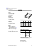
Multilayer Chip Capacitors C0G/NP0/CH Features ● ● ● ● l Good thermal stability High insulation resistance Low dissipation factor Low inductance Applications ● Resonant circuits ● Filter circuits ● Timing elements ● Coupling and filtering, particularly in RF circuits Terminations ● For soldering: silver/nickel/tin ● For conductive adhesion: silver palladium Packing ● Blister and cardboard tape, for details refer to chapter on “Taping and Packing”, page 111.
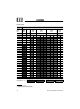
Product range C0G/NP0/CH Size1) inch mm 0402 1005 0603 1608 0805 2012 1206 3216 1210 3225 Type B37920 B37930 B37940 B37871 B37949 VR (Vdc) 50 1,0 pF 1,0 pF 50 50 100 200 50 100 200 50 200 1,2 pF 1,5 pF 1,8 pF 2,2 pF 2,0 pF 2) 2,7 pF 3,0 pF 2) 3,3 pF 4,0 pF 2) 3,9 pF 5,0 pF 2) 4,7 pF 6,0 pF 2) 5,6 pF 7,0 pF 2) 6,8 pF 8,0 pF 2) 8,2 pF 9,0 pF 2) 10 pF 12 pF 15 pF 18 pF 22 pF 27 pF 33 pF 39 pF 47 pF 56 pF 68 pF 82 pF Chip thickness (s ): 0,5 ± 0,
Product range C0G/NP0/CH Size1) inch mm 0402 1005 0603 1608 0805 2012 1206 3216 1210 3225 Type B37920 B37930 B37940 B37871 B37949 VR (Vdc) 100 pF 120 pF 150 pF 180 pF 220 pF 270 pF 330 pF 390 pF 470 pF 560 pF 680 pF 820 pF 50 50 50 100 200 50 100 200 50 100 200 1,0 nF 1,2 nF 1,5 nF 1,8 nF 2,2 nF 2,7 nF 3,3 nF 3,9 nF 4,7 nF 5,6 nF 6,8 nF 8,2 nF 10 nF Chip thickness (s ): 0,5 ± 0,1 mm 0,6 ± 0,1 mm 0,8 ± 0,1 mm 1,2 ± 0,1 mm 1,6 ± 0,1 mm 1) I × b (inch) / l
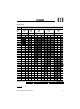
Ordering codes for C0G/NP0/CH, 50 Vdc, AgNiSn terminations Size 0402/1005 CR1) Ordering code 2) B37920B37930- 0603/1608 1,0 pF 1,2 pF 1,5 pF 1,8 pF 2,2 (2,0) pF 2,7 (3,0) pF 3,3 (4,0) pF 3,9 (5,0) pF 4,7 (6,0) pF 5,6 (7,0) pF 6,8 (8,0) pF 8,2 (9,0) pF 10,0 pF 12,0 pF 15,0 pF 18,0 pF 22,0 pF 27,0 pF 33,0 pF 39,0 pF 47,0 pF 56,0 pF 68,0 pF 82,0 pF 100,0 pF 120,0 pF 150,0 pF 180,0 pF 220,0 pF 270,0 pF 330,0 pF 390,0 pF 470,0 pF 560,0 pF 680,0 pF 820,0 pF -K5010-C60 ▲ -K5010-C60 -K5010-C260 -K5010-C560 -K
Ordering codes for C0G/NP0/CH, 50 Vdc, AgNiSn terminations (cont´d) Size 0402/1005 CR1) Ordering code 2) B37920B37930- 0603/1606 1,0 nF 1,2 nF 1,5 nF 1,8 nF 2,2 nF 2,7 nF 3,3 nF 3,9 nF 4,7 nF 5,6 nF 6,8 nF 8,2 nF 10,0 nF Chip thickness: ❑: 0,6 ± 0,1 mm 0805/2012 1206/3216 B37940-K5102-J60 -K5122-J60 -K5152-J60 -K5182-J62 -K5222-J62 ❍: 0,8 ± 0,1 mm 1210/3225 B37871❑ ❍ ❍ ◆ ◆ -K5102-J60 -K5122-J60 -K5152-J60 -K5182-J60 -K5222-J60 -K5272-J60 -K5332-J60 -K5392-J60 -K5472-J62 -K5562-J62 B37949❍ ❍ ❍ ❍
Ordering codes for C0G/NP0/CH, 100 Vdc, AgNiSn terminations Size 0805/2012 CR Ordering code 1) B37940B37871- 1206/3216 1,0 pF 1,2 pF 1,5 pF 1,8 pF 2,2 pF 2,7 pF 3,3 pF 3,9 pF 4,7 pF 5,6 pF 6,8 pF 8,2 pF 10,0 pF 12,0 pF 15,0 pF 18,0 pF 22,0 pF 27,0 pF 33,0 pF 39,0 pF 47,0 pF 56,0 pF 68,0 pF 82,0 pF 100,0 pF 120,0 pF 150,0 pF 180,0 pF 220,0 pF 270,0 pF 330,0 pF 390,0 pF 470,0 pF 560,0 pF 680,0 pF 820,0 pF 1,0 nF -K1010-C60 -K1010-C260 -K1010-C560 -K1010-C860 -K1020-C260 -K1020-C760 -K1030-C360 -K1030-C9
Ordering codes for C0G/NP0/CH, 200 Vdc, AgNiSn terminations Size 0805/2012 CR Ordering code1) B37940B37871- 1206/3216 1,0 pF 1,2 pF 1,5 pF 1,8 pF 2,2 pF 2,7 pF 3,3 pF 3,9 pF 4,7 pF 5,6 pF 6,8 pF 8,2 pF 10,0 pF 12,0 pF 15,0 pF 18,0 pF 22,0 pF 27,0 pF 33,0 pF 39,0 pF 47,0 pF 56,0 pF 68,0 pF 82,0 pF 100,0 pF 120,0 pF 150,0 pF 180,0 pF 220,0 pF 270,0 pF 330,0 pF 390,0 pF 470,0 pF 560,0 pF 680,0 pF 820,0 pF -K2010-C60 -K2010-C260 -K2010-C560 -K2010-C860 -K2020-C260 -K2020-C760 -K2030-C360 -K2030-C960 -K204
Ordering codes for C0G/NP0/CH, 200 Vdc, AgNiSn terminations (cont´d) Size 0805/2012 CR Ordering code1) B37940B37871- 1,0 nF 1,2 nF 1,5 nF 1,8 nF 2,2 nF 1206/3216 -K2102-J62 Chip thickness: ❑: 0,6 ± 0,1 mm 1210/3225 B37949◆ -K2102-J62 -K2122-J62 -K2152-J62 -K2182-J62 -K2222-J62 ❍: 0,8 ± 0,1 mm ❍ ◆ ◆ ◆ ● ◆: 1,2 ± 0,1 mm ●: 1,6 ± 0,1 mm 1) The tables contain the ordering codes for the standard capacitance tolerance: C = ± 0,25 pF for < 10 pF; J = ± 5 % for ≥ 10 pF.
Ordering codes for C0G/NP0/CH, 50 Vdc, AgNiSn terminations, bulk case packing Size CR1) 1,0 pF 1,2 pF 1,5 pF 1,8 pF 2,2 pF 2,7 pF 3,3 pF 3,9 pF 4,7 pF 5,6 pF 6,8 pF 8,2 pF 10,0 pF 12,0 pF 15,0 pF 18,0 pF 22,0 pF 27,0 pF 33,0 pF 39,0 pF 47,0 pF 56,0 pF 68,0 pF 82,0 pF 100,0 pF 120,0 pF 150,0 pF 180,0 pF 220,0 pF 270,0 pF 330,0 pF 390,0 pF 470,0 pF 560,0 pF 680,0 pF 820,0 pF 0603/1608 Ordering code2) B37930-K5010-C01 ❍ -K5010-C201 ❍ -K5010-C501 ❍ -K5010-C801 ❍ -K5020-C201 ❍ -K5020-C701 ❍ -K5030-C301 ❍ -K5030
Ordering codes for C0G/NP0/CH, 50 Vdc, AgNiSn terminations, bulk case packing (cont´d) Size CR1) 1,0 nF 1,2 nF 1,5 nF 1,8 nF 2,2 nF 0603/1608 0805/2012 Ordering code2) B37930B37940-K5102-J01 1206/3216 B37871❑ -K5102-J01 -K5122-J01 -K5152-J01 -K5182-J01 -K5222-J01 ❑ ❑ ❑ ❑ ❑ Chip thickness: ❑: 0,6 ± 0,1 mm 1) E24 series available on request 2) The tables contain the ordering codes for the standard capacitance tolerance: C = ± 0,25 pF for < 10 pF; J = ± 5 % for ≥ 10 pF.
Characteristics Capacitance change ∆C/C25 versus temperature T (tolerance range ) Capacitance change ∆C/C0 versus superimposed dc voltage V Impedance |Z | versus frequency f Dissipation factor tan δ versus temperatureT Siemens Matsushita Components 25
Insulation resistance Rins versus temperature T Capacitance change ∆C/C1 versus time t Rins 26 Siemens Matsushita Components